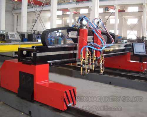
Groove Weld Types: Square, V, Bevel, U and J Explained
Table of Contents
- What Makes a Joint a Groove Weld
- Groove Weld Types and Where Each One Fits
- Double-Sided Grooves and the Cost of Turning the Part
- Why Bevel, U and J Grooves Save Filler Metal
- Bevel Grooves
- U and J Grooves
- Flare Grooves for Tube, Pipe and Formed Edges
- Reading Groove Symbols Without Guessing
- Groove Angle Versus Bevel Angle
- What the Symbol Does Not Tell You
- Position, Access and Workholding for Groove Welds
- Getting the Groove Right on the Next Job
- FAQ
- What is the difference between a groove weld and a fillet weld?
- Does a groove weld always require full penetration?
- Can a groove joint be welded from one side only?
- Which groove type should be used for thick plate?
A groove weld is only as good as the shape cut into the joint faces before the arc starts. The groove type decides how much metal has to be deposited, how easily the arc reaches the root, how much the part will distort, and how much of the joint an inspector can actually confirm. That is why the choice between a square, V, bevel, U, J or flare groove is a production decision rather than a drawing formality. Each form carries a thickness assumption, an access requirement and a characteristic failure mode, and the drawing has to satisfy all three at once.
What Makes a Joint a Groove Weld
A groove weld fills a prepared opening. The opening is cut, machined, ground or formed into the edges of two members before welding, and the welder deposits metal into that space. Everything downstream, filler consumption, arc access to the root, distortion direction and inspection confidence, is set by the geometry of that opening.
The term is often confused with the joint type. A butt joint describes how two members meet, edge to edge in the same plane. A groove weld describes the metal deposited in the gap between them. Most butt joints are welded with a groove, but a T joint or a corner joint can also carry a groove weld when the design needs penetration past the corner. Keeping those two vocabularies apart makes a welding drawing much easier to read.
Four dimensions define most groove geometry:
- Root opening (root gap): the space between the members at the bottom of the groove.
- Root face (land): the blunt, unwelded portion left at the root before welding.
- Bevel angle: the angle cut on one member, measured from a line perpendicular to its surface.
- Groove angle: the total included angle between the two prepared faces. On a symmetric single-V joint it is twice the bevel angle.
Depth of penetration is the fifth variable, and it changes cost more than any other. A complete joint penetration (CJP) groove weld fuses through the full thickness. A partial joint penetration (PJP) groove weld is specified to a shallower depth, with a root face left intact below it. Two drawings can show the same V symbol and still ask for very different amounts of work.
Groove Weld Types and Where Each One Fits
The groove family covers square, single-V, double-V, single-bevel, double-bevel, single-U, double-U, single-J, double-J, flare-V and flare-bevel. The straight-sided and chamfered forms do most of the work in plate fabrication. The radiused forms appear where filler volume or wall thickness justifies machining. The flare forms belong to tube, pipe and formed sheet.
| Groove type | Typical use | What it buys | What it costs |
|---|---|---|---|
| Square | Thin plate and sheet with clean fit-up | No edge preparation at all | Root fusion depends entirely on gap control |
| Single-V | Moderate thickness, access from one side | Familiar, easy to inspect, simple to bevel | Largest fill volume of the chamfered forms |
| Double-V | Thicker plate with access to both faces | Roughly half the fill of a single-V, balanced shrinkage | Turning, plus back gouging of the first root |
| Single-bevel | T joints, corner joints, unequal thickness | Chamfers one member only, leaves the other face flat | Off-center heat and pull toward the bevel |
| Single-U | Heavy wall with one-side access | Narrow included angle, noticeably less filler | Machining or planing, tighter fit-up tolerance |
| Single-J | Heavy plate or pipe with one flat member | Narrow groove on one side only | Machining, and low tolerance for misalignment |
Read the table as a trade between preparation effort and deposition effort. Square grooves spend nothing on preparation and everything on filling and gap control. U and J grooves spend on machining and recover the money in filler metal and arc time, but only if the joint runs long enough to amortize the setup.
The mechanism behind that trade is geometry. A groove weld is a filling problem: the welder must deposit enough metal to fill the cross-section of the prepared opening. That area grows with the depth of the groove and with the width at its top, so a wide included angle on thick material multiplies both filler consumption and shrinkage stress. A square groove has no angle to work with, so the only way to reach the root at depth is a wider gap, which is a dead end once the material passes the thickness where a single pass can fuse the root. Chamfering gives the electrode a clear path to the root without an impractical gap, and that is the whole reason the V, bevel, U and J forms exist.
Narrow grooves are not automatically better. A U or a narrow-V leaves the arc less room to recover from a mismatch, so the fit-up tolerance in the shop has to be genuinely repeatable. If the tooling cannot hold the groove consistently, a slightly wider V that the team can trust will usually produce fewer repairs than a narrow groove that looks efficient on paper.
What is actually permitted on a drawing is set by the qualified welding procedure, not by a general description. Structural codes such as AWS D1.1 publish prequalified groove details for specific processes, so a joint matching one of those details can be used without fresh qualification testing, and anything outside them must be qualified by test. ISO 9692-1 collects joint preparation types and dimensions in a comparable way. Those documents, together with the procedure qualification record, decide the groove on your drawing.
Double-Sided Grooves and the Cost of Turning the Part
Double-V and double-U joints replace one deep groove with two shallower ones, one on each face. Two things improve at once. The fill volume drops because each groove is filled from its narrow side, and the heat input sits closer to balanced about the mid-plane, which pulls angular distortion back toward the center line. On thick plate with a long seam, that combination usually settles the decision.
The price is access and handling. Someone has to turn the part, and the root of the first side has to be gouged or ground back to sound metal before the second side goes in. Skip that step and the second side is deposited over an unfused root, which later reads as a planar indication along exactly the line the double groove was meant to guarantee.
So the question is rarely which groove is stronger. It is whether the workpiece can be rotated cheaply. If it can, double-sided grooves are usually the economical answer once the wall gets thick. If the part is large, restrained, or has one face against a structure, a single-sided groove with backing or a single-U is the realistic option.
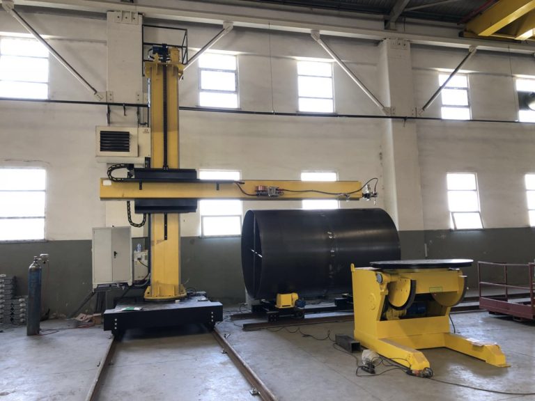
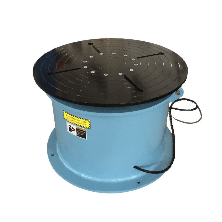
That makes the handling equipment part of the joint design. A turntable sized for the assembly turns a fixed job into a rotated one. A crane and a sling turn the same job into a two-hour interruption and a distortion problem.
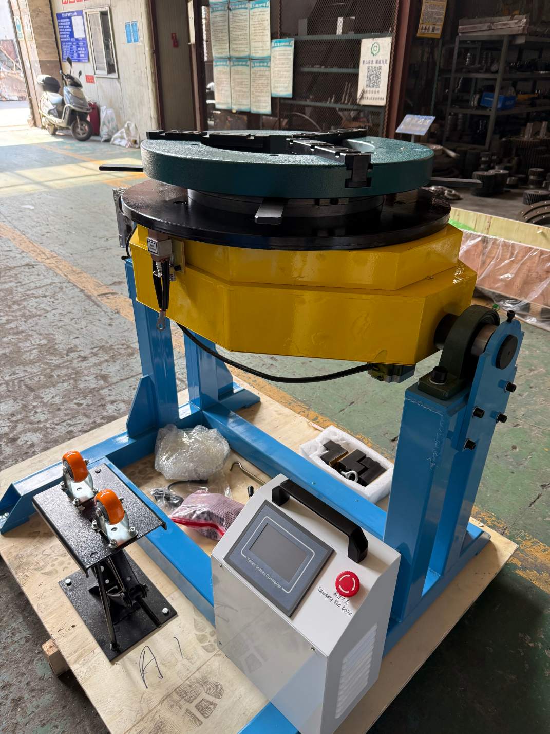
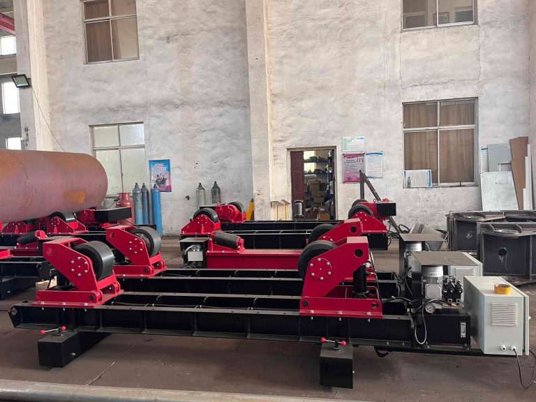
Cylindrical work has a second route. Turning rolls support the shell or pipe and rotate it between passes, so a circumferential groove stays in the flat position without a lift. Choosing between rotating the work and welding out of position is a productivity question long before it becomes a quality question, and the cost difference shows up in repair rates as well as cycle time.
Rotating the workpiece changes the economics of a groove more than most procedure changes do. <Pipe Welding Rotator vs Manual Welding | Productivity and Cost Comparison> covers how a pipe welding rotator compares with manual pipe welding on productivity and cost.
Why Bevel, U and J Grooves Save Filler Metal
Bevel Grooves
A bevel groove chamfers one member and leaves the other square. That asymmetry is the point. It suits T joints and corner joints where the upstanding member has to keep a flat face, and it suits unequal thickness, where the bevel depth is governed by the thinner member while the thicker one carries the extra land.
The cost is asymmetric heat. The beveled side takes more weld metal and shrinks more, so the joint pulls toward the chamfer. Plan for that in fit-up and in the welding sequence instead of correcting it afterwards.
U and J Grooves
U and J grooves replace the straight chamfer with a machined radius at the root. The curved wall lets the arc reach the sidewall at a narrower included angle than a V allows, and the narrower angle is where the filler saving comes from. A J groove is the same idea applied to one member only, paired with a square edge, so it behaves like a bevel with a radiused root.
Preparation is where they cost. U and J need machining or planing, a tool that matches the radius, and better fit-up discipline, because a narrow groove leaves less room to recover from a mismatch. They earn their place on heavy wall, long seams and repeat batches, where filler and cycle time saved over the run outweigh the machining setup. On one short joint, the setup often costs more than the filler it saves.
Flare Grooves for Tube, Pipe and Formed Edges
Flare grooves are formed rather than cut. When two members with curved or radiused edges come together, the flare of those edges creates the groove. A flare-V joins two curved edges. A flare-bevel sets one curved edge against a flat face, which is the standard tube-to-plate and tube-to-header configuration.
Because the groove is a product of the forming operation, its consistency depends on forming accuracy rather than a later cutting step. Two consequences follow. Fit-up problems in flare joints usually trace back to ovality, springback or a radius that drifted, so the forming and straightening stages carry the tolerance. And the groove is open and shallow compared with a machined V, so a visual check confirms less than it seems to; penetration depends on the arc reaching the root of the flare, which is a procedure question rather than a fitter’s question.
Boiler membrane panels show both halves of this. Fin bars welded between tubes depend on consistent fin geometry, and a calibration step before welding keeps the bar straight and the groove uniform along the whole panel.
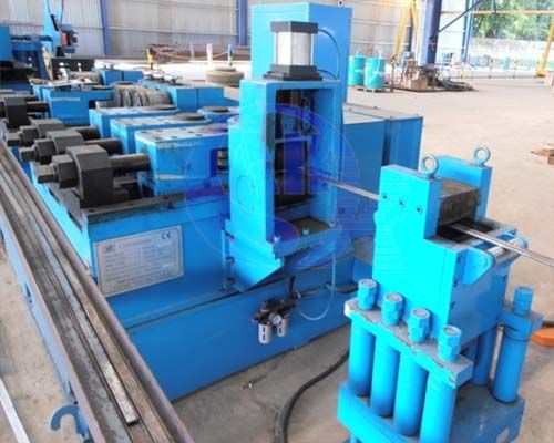
Panel forming sets the tube pitch and the edge condition that the panel groove inherits, so bending accuracy reappears later as a welding problem.
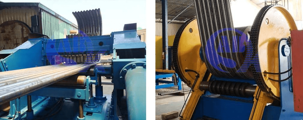
A membrane panel line is therefore a sequence of tolerance decisions rather than a single welding operation. Each upstream step either protects the groove or erodes it.
Membrane panel quality is decided before the torch reaches the joint. <Boiler Production Lines: Tube to Panel Manufacturing Explained> covers the tube to panel manufacturing sequence used in boiler production lines.
Reading Groove Symbols Without Guessing
A groove symbol carries more information than most drawings make obvious. The reference line and arrow point to the joint. The groove symbol sits on the line, with the weld size to its left, the groove angle inside it and the root opening beside it. A symbol above the line describes the far side of the joint, which is how a double-V is drawn. The tail carries the process or specification reference when one is needed, and the flags at the junction mark an all-around weld or a field weld.
Groove Angle Versus Bevel Angle
The angle shown inside the groove symbol is the included groove angle. The bevel angle is what gets cut on each member, and on a symmetric joint it is half the included angle. A 60 degree V groove therefore means a 30 degree bevel on each plate. Reading one as the other is the most common reason a joint arrives at the bench with the wrong geometry, and it is worth confirming on the detail drawing rather than the assembly view.
What the Symbol Does Not Tell You
| What the drawing shows | What it does not establish | What to check instead |
|---|---|---|
| A V groove symbol with an included angle | That the angle suits the process and thickness | The qualified procedure and any prequalified detail it relies on |
| A groove weld size beside the symbol | Full penetration through the thickness | Whether the joint is specified as CJP or PJP |
| A backing bar drawn under the root | That the root will fuse cleanly | Backing material, fit-up, and whether the backing stays in place |
| A field weld flag on the symbol | That the shop procedure transfers to site | The site procedure, welding position and conditions of use |
Each row is a case where the drawing is complete as geometry and silent as a decision. The symbol tells the welder what shape to produce. It does not tell anyone whether that shape has been qualified for the material, the position and the process actually in front of them.
Position, Access and Workholding for Groove Welds
Groove welds are easiest in the flat position. Rolled or flat, gravity holds the pool where the welder wants it, slag lifts away from the sidewall instead of settling into it, and the arc reaches the root with the least manipulation. Move the same joint to vertical or overhead and the risks change: lack of fusion on the sidewall, slag entrapment at the root of a narrow groove, and a pool that has to be controlled rather than simply carried.
That is why the cheapest quality improvement on many groove joints is not a procedure change but a rotation. Keeping the groove flat for as much of the pass as possible removes a whole class of defects instead of correcting them afterwards.
Circumferential grooves on pipe are the clearest example. A steady, uninterrupted rotation keeps the arc in the same part of the groove all the way around, which is what makes a girth seam uniform. Stop-start rotation shows up as bead width variation and inconsistent penetration long before it appears in a test report.
Consistency around a girth seam comes from the machine, not from the welder’s patience. <Automatic Girth Welding Machines: Boost Efficiency for Pipeline Projects> covers automatic girth welding machines used on pipeline projects.
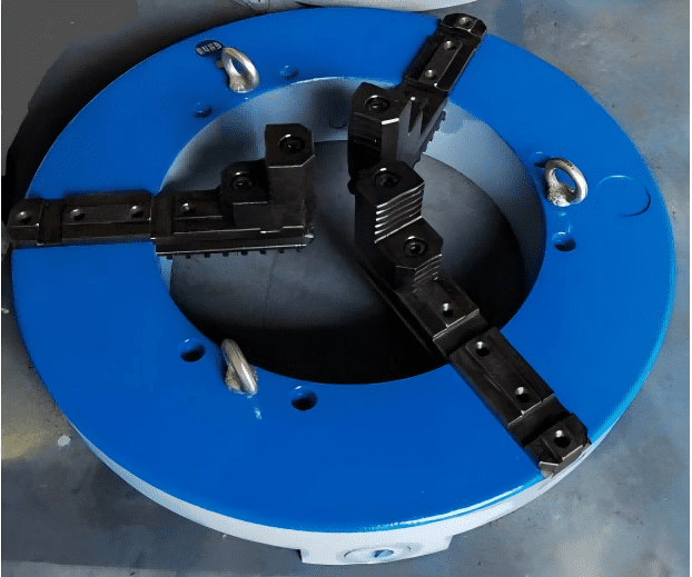
Workholding deserves the same attention as the groove itself. A positioner or rotator keeps the joint where it can be welded, and a chuck holds pipe, flange or fitting work on its axis so the groove runs true. Runout is the detail that gets missed: an eccentric grip makes the groove oscillate under the torch, so penetration changes around the circumference even though the settings never moved.
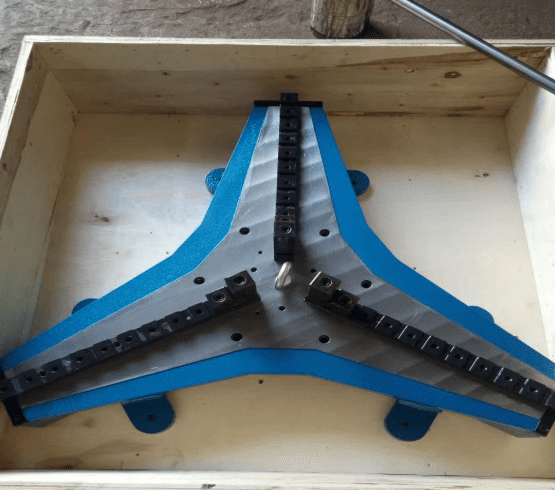
Smaller workpieces follow the same rule with less margin. On light parts the mass of the fixture can dominate the assembly, and any imbalance in the grip shows up as a wandering groove rather than a visible wobble.
Getting the Groove Right on the Next Job
The groove type, the welding position and the equipment that holds the part are one decision, not three. Before a positioner, rotator or turntable is specified, the joint detail has to be settled: groove form, material thickness, root opening and root face, whether the weld is CJP or PJP, the position it will be welded in, and the diameter, length and weight of the workpiece.
Send that detail to the team at WUXI ABK MACHINERY CO., LTD and you will get a configuration answer rather than a catalogue page. Email [email protected] or call +86 13616174307 with the joint sketch and the workpiece data, and the reply will confirm which holding and rotating arrangement suits the groove you have specified.
FAQ
What is the difference between a groove weld and a fillet weld?
A fillet weld sits in the corner where two surfaces meet and needs no edge preparation, and its capacity is described by its leg or throat. A groove weld fills a prepared opening between the edges of two members, so those edges must be cut, machined or formed before welding begins. The practical difference is load path. A complete joint penetration groove weld carries load through the full thickness, while a fillet weld transfers it through the throat and concentrates stress at the toe.
Does a groove weld always require full penetration?
No. A partial joint penetration groove weld is specified to a depth shallower than the material, with a root face left below it, and it is normal on stiffeners, splices and connections designed around that effective throat. The drawing or the qualified procedure should state which one applies. Two joints can carry the same V symbol and still differ completely in preparation, filler consumption and inspection method, so confirm CJP or PJP before pricing the work.
Can a groove joint be welded from one side only?
Yes, with conditions. A single-sided groove can reach complete penetration with a backing bar, ceramic backing tape, or a process with enough root control, and it can also be welded without backing when the procedure is qualified for that root condition. Where neither is available, a partial penetration groove or a double-sided joint with back gouging is the honest alternative. Accessibility and the qualified procedure decide it, not preference.
Which groove type should be used for thick plate?
Usually a double-V, double-U or single-U, depending on access. Chamfered and radiused forms give the arc a clear path to the root without an impractical gap, and the double-sided versions cut fill volume while balancing shrinkage. A square groove stops being practical once the material is too thick for the arc to fuse the root reliably, and a single-V becomes expensive because fill volume grows with the included angle. The qualified procedure and any prequalified details in the applicable code set the final limits.
If you’re interested, check out these related articles:
H-Beam Assembly: Automated Web and Flange Fit-Up Precision
Fit-Up Rotator for Accurate Vessel Alignment & Stable Welding
Industrial Welding Rotator Types & Structural Designs
Shot Blasting Solutions for Steel Structure Surface Treatment