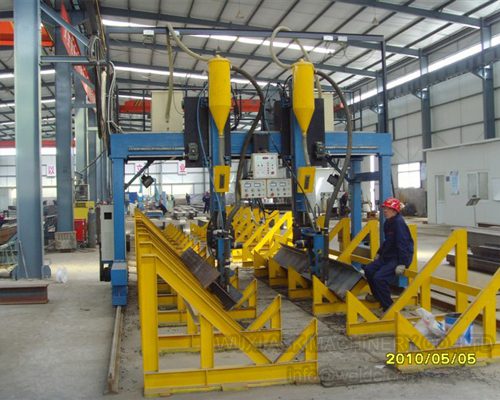
Boiler Production Lines: Tube and Panel Fabrication Processes
Table of Contents
Manufacturing boilers demands a coordinated sequence of operations that converts raw tubing into pressure-rated panel assemblies and finished systems. A production line built around this sequence determines throughput rates, dimensional consistency, and compliance with pressure vessel codes. Each stage—tube fabrication, panel welding, header integration, final assembly—requires equipment matched to material grades, wall thicknesses, and weld specifications. The machinery selections and process controls at each station directly affect cycle times, reject rates, and the certifications a finished boiler can carry.
Where Boiler Tube Fabrication Starts
Tube geometry and fin attachment quality set the thermal performance ceiling for the entire boiler. The process begins with material receiving inspection, typically verifying heat numbers, chemical composition certificates, and dimensional tolerances against the purchase specification. High-grade steel alloys—often chromium-molybdenum grades for elevated-temperature service—arrive as straight lengths requiring bending, cutting, and surface preparation before they become functional heat transfer elements.
Bending machines shape tubes into the radii and angles specified by the boiler designer. CNC-controlled benders with mandrel support prevent wall thinning and ovality at the bend apex, both of which reduce pressure ratings if they exceed code limits. Real-time feedback from laser measurement systems allows the machine to compensate for springback, holding bend angles within fractions of a degree. On one project where a fabricator was scrapping nearly 8% of bent tubes due to out-of-tolerance radii, installing a CNC bender with integrated laser scanning dropped that figure to under 3% within the first quarter of operation.
Finning machines attach metal fins to the tube exterior, expanding the heat transfer surface area. The attachment method—resistance welding, high-frequency induction welding, or mechanical interference fit—depends on the fin material, tube material, and operating temperature. A fin that separates from the tube under thermal cycling creates a local hot spot, accelerating tube degradation. Weld-attached fins require consistent penetration depth and fusion width across thousands of meters of tube length per boiler, which is why automated finning lines dominate production environments handling more than a few units per month.
Tube welding equipment joins individual tube sections or attaches stub ends for header connections. Orbital welding heads produce repeatable root passes on tube-to-tube joints, and the weld parameters—current, travel speed, shielding gas flow—are logged for traceability. Material handling systems move tubes between stations on roller conveyors or overhead cranes, reducing manual handling that can introduce surface damage or contamination.
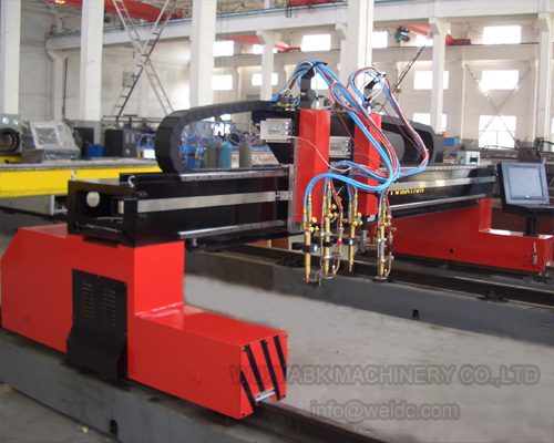
How Membrane Wall Panel Production Works
Automated membrane wall welding cuts panel fabrication time by an order of magnitude compared to manual methods while tightening weld quality variance. Membrane walls form the gas-tight enclosure around the combustion chamber, constructed from parallel tubes joined by continuous steel strips welded along both edges. This construction creates a rigid, pressure-retaining surface that also serves as the primary heat absorption zone.
The welding process for membrane panels involves simultaneous seams running the full length of the panel, sometimes exceeding 15 meters. Submerged arc welding or gas metal arc welding heads travel along the tube-to-strip joints at speeds that would be impossible to sustain manually. Automatic welding systems maintain consistent arc length, wire feed rate, and travel speed, producing uniform bead geometry and penetration depth across the entire seam. Robotic welding cells handle panels with complex geometries or multiple tube diameters, repositioning the workpiece and adjusting parameters between passes without operator intervention.
The consistency advantage matters for pressure integrity. A membrane wall with variable weld penetration contains weak points that may not fail during hydrostatic testing but could develop leaks under thermal cycling in service. Automated systems reduce this variability, and the weld parameter logs they generate simplify the documentation required for code compliance.
| Welding Method | Primary Advantage | Where It Fits |
|---|---|---|
| Manual Arc Welding | Adaptable to irregular access | Repair work, low-volume fabrication |
| Submerged Arc Welding | High deposition rate, deep penetration | Long straight seams, thick sections |
| Gas Metal Arc Welding | Moderate speed, good visibility | General panel fabrication, position welds |
| Robotic Welding | Repeatability, unattended operation | High-volume production, complex panel shapes |
Integrating Headers, Drums, and Subassemblies
The fit-up and welding of headers and drums to tube panels determines whether the boiler will pass hydrostatic test on the first attempt. Headers are thick-walled pipes drilled and machined to accept tube stubs, distributing or collecting flow across the tube bank. Drum fabrication involves rolling plate into cylindrical shells, welding longitudinal and circumferential seams, and attaching nozzles and internals. Both components carry the full operating pressure of the boiler, so their welds receive the most scrutiny during inspection.
Header fabrication starts with cutting pipe to length, then drilling or machining the stub holes on a pattern that matches the tube panel layout. Hole location tolerances are tight—misalignment by a few millimeters can prevent tube stubs from seating properly, requiring rework that delays the entire assembly schedule. After drilling, nozzles and tube stubs are fit and welded, often using preheat and controlled interpass temperatures to avoid cracking in the thick sections.
Drum production follows a similar discipline. The shell welds are radiographed or ultrasonically examined to verify full penetration and absence of defects. Nozzle-to-shell welds receive the same treatment. Once the drum passes non-destructive examination, it moves to the assembly area where it joins the tube panels and headers.
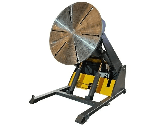
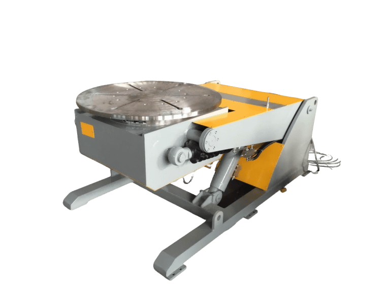
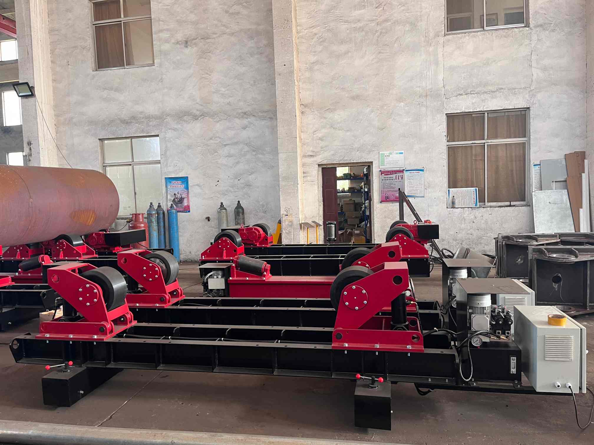
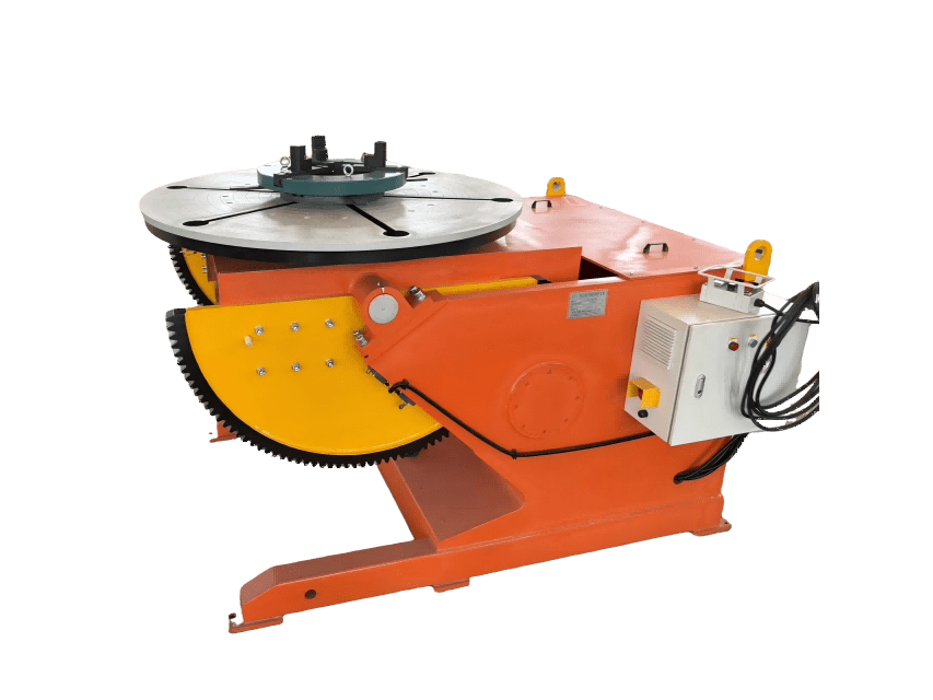
The assembly line itself requires positioning equipment—rotators, manipulators, positioners—that can handle the weight and dimensions of boiler subassemblies. A 60-ton fit-up rotator, for example, allows welders to access circumferential joints in the flat or horizontal position rather than working overhead, improving weld quality and reducing fatigue. The sequence of fit-up, tack welding, and final welding follows a procedure qualified to the applicable code, whether ASME Section I for power boilers or EN 12952 for water-tube boilers in European markets.
What Quality Control Looks Like on the Production Floor
Inspection and testing at each fabrication stage catch defects before they become embedded in a finished assembly that would require costly rework or scrapping. Quality control begins at material receiving, where mill test reports are verified against the purchase order and spot checks confirm that the material markings match the documentation. Any discrepancy halts that material lot until resolution.
During tube fabrication, dimensional checks verify bend angles, tube lengths, and fin attachment. Weld inspections—visual examination first, then non-destructive testing where specified—confirm that joints meet the acceptance criteria in the welding procedure specification. Ultrasonic testing can detect subsurface flaws in tube-to-header welds, while radiography provides a permanent record of weld quality for pressure-retaining joints.
Compliance with codes like ASME or the Pressure Equipment Directive is not optional for boilers entering most markets. The code dictates material traceability requirements, welder qualification, welding procedure qualification, inspection hold points, and documentation. A boiler fabricated without following these requirements cannot be stamped or certified, which means it cannot be legally installed in jurisdictions that enforce the code.
Digital systems that track production data—weld parameters, inspection results, heat numbers, dimensional measurements—simplify the documentation burden and make it easier to trace any issue back to its source. If a weld defect appears during final inspection, the production records can identify which welder, which machine, and which material lot were involved, enabling corrective action that prevents recurrence.
Designing a Production Line That Matches Your Output Targets
A production line layout that minimizes material travel distance and balances cycle times across stations delivers higher throughput from the same floor space and labor headcount. The design process starts with the product mix—what boiler types, what size range, what annual volume—and works backward to equipment selection and arrangement.
Tube fabrication equipment capacity must feed the panel welding stations without creating a bottleneck or leaving welders idle. If the bending and finning lines can produce 500 meters of finished tube per shift but the panel welding stations can only consume 400 meters, either the upstream equipment runs at reduced utilization or work-in-process inventory accumulates. Neither outcome is desirable. Matching capacities across the line, with some buffer for variability, keeps material flowing and labor productive.
The physical layout matters as well. A linear flow from receiving through fabrication, subassembly, final assembly, and testing minimizes backtracking and crane movements. Workstations arranged in a U-shape or cellular layout can reduce travel distance further for certain product families. The choice depends on the facility footprint, the product mix, and the degree of automation planned.
Turnkey production line projects bundle equipment selection, layout design, installation, commissioning, and operator training into a single scope. This approach reduces the coordination burden on the buyer and assigns responsibility for system performance to the supplier. Ongoing maintenance agreements extend that relationship, providing scheduled service, spare parts supply, and technical support that keep the line running at rated capacity.
Frequently Asked Questions
What equipment does boiler tube production require?
Tube production lines typically include CNC tube bending machines with mandrel support for tight radii, finning machines matched to the fin attachment method specified by the boiler designer, and tube welding equipment for joining sections and attaching stubs. Material handling—roller conveyors, overhead cranes, or automated guided vehicles—moves tubes between stations. The specific models and capacities depend on tube diameters, wall thicknesses, and production volumes.
How does automation change boiler production economics?
Automation shifts the cost structure from direct labor toward capital equipment and maintenance. Welding robots and automatic panel lines produce consistent quality at speeds manual welders cannot sustain, reducing per-unit labor cost and scrap rates. The payback period depends on production volume—high-volume operations recover the investment faster—but even moderate volumes often justify automation when factoring in quality improvements and reduced rework.
What certifications matter for boiler manufacturing equipment?
Equipment used in pressure vessel fabrication should carry ISO 9001 certification for quality management systems. CE marking indicates compliance with European safety directives. Beyond the equipment itself, the fabrication shop needs code stamps or authorizations—ASME U or S stamps, PED module certifications—that permit it to build and certify boilers for specific markets. Equipment suppliers that understand these requirements can configure machines to support the documentation and traceability the codes demand.
What drives lead time for a custom production line?
Lead time depends on equipment complexity, customization scope, and supplier backlog. Standard machines with minor modifications might ship in 12 to 16 weeks; highly customized lines with integrated automation can take 6 months or longer. Early engagement with the supplier, clear specifications, and realistic scheduling that accounts for installation and commissioning reduce the risk of delays affecting your production ramp-up.
Is upgrading an existing line practical?
Many existing lines accept technology upgrades without full replacement. Adding CNC controls to manual benders, retrofitting automatic welding heads to existing panel fixtures, or installing digital tracking systems can improve throughput and quality incrementally. A line assessment identifies the bottlenecks and quality gaps where upgrades deliver the best return, allowing phased investment rather than a single large capital outlay.
How critical is after-sales support for this equipment?
Production equipment that sits idle waiting for parts or service erases the throughput gains it was purchased to deliver. Suppliers with regional spare parts inventory, trained service technicians, and remote diagnostic capability minimize downtime when issues arise. Maintenance agreements that include scheduled inspections catch wear items before they fail, avoiding unplanned stops during production runs. If you are evaluating equipment options and want to discuss how support and service factor into total cost of ownership, reach out to our team at [email protected] or +86 13616174307.
If you’re interested, check out these related articles:
Welding Rotator vs Manual Pipe Welding: Productivity & Cost Efficiency