TIG Weld Troubleshooting: Defects, Causes, and Fixes
Table of Contents
- What the Bead, the Tungsten, and the Gas Trail Tell You First
- Porosity and Discoloration in TIG Welding
- Tungsten Contamination, Arc Wander, and Hard Starts
- Incomplete Fusion and Lack of Penetration Under the Bead
- Undercut, Crater Cracks, and Distortion From Heat Input
- Cracks That Appear After the Weld Cools
- TIG Weld Troubleshooting Lookup for the Shop Floor
- When the Limit Is the Position and Not the Torch
- Tell Us the Defect and the Conditions Behind It
- FAQ
- Why does my TIG weld turn gray or black on stainless steel?
- How can I tell whether my gas flow is too high?
- Why does the tungsten ball unevenly or split on aluminum?
- Is porosity always a shielding gas problem?
TIG weld troubleshooting comes down to one decision: is the problem the gas, the electrode, or the arc? Most faults that send an operator back to the settings panel trace to one of those three, and they are the cheapest to rule out first. Porosity, discoloration, arc wander, incomplete fusion, undercut, and crater cracks all leave physical evidence in the bead, on the tungsten, or in the shielding trail, and that evidence can be read in a fixed order. This guide works through the common TIG faults in that order, separates a confirmed cause from a plausible one, and marks the point where the fix is a process change rather than another setting.
What the Bead, the Tungsten, and the Gas Trail Tell You First
TIG gives the operator very little to hide behind. The arc is short, the puddle is small, and the process depends on three inputs staying stable at the same time: shielding gas reaching the puddle, a tungsten tip that can hold a stable arc root, and an arc length short enough to keep heat concentrated. A fault in any one of them shows up as a defect, but the defect rarely names which one it was. The evidence that does name it is already in front of you.
Start with the tungsten. A tip that is bright and evenly shaped is holding its arc; a tip that is split, mushroomed, or blackened has been contaminated or overheated, and any weld made with it carries that instability into the bead. On AC work the tip should carry a rounded ball, and a ball that has grown far beyond the electrode diameter spreads the arc and softens penetration.
Then read the bead. The way the toes wet into the base metal, the crown height, and the regularity of the ripples record heat input and travel stability better than the machine display does. Finally, look past the weld on stainless and titanium. A halo of color beyond the bead is oxygen that reached metal still hot enough to absorb it, which points at the gas path even when the bead itself looks clean.
The rule that makes this useful is isolation. Change one variable, re-weld on scrap of the same alloy, and treat the cause as confirmed only when the defect disappears and returns when the variable is put back. A plausible cause that has not been isolated is a guess, and guessing with the settings panel is how a small gas leak becomes an afternoon of parameter changes.
Porosity and Discoloration in TIG Welding
Shielding fails in three ways, and they produce similar-looking porosity but need different fixes: too little flow, too much flow, or a path that lets air into the column.
Too little gas is the simple case. The cup cannot fill the space between the tungsten and the puddle, air reaches the arc, and the pores concentrate where the joint is tight, deep, or hard to reach. Too much flow is the case operators miss. Gas leaving the cup at high velocity creates turbulence at the mouth, and that turbulence can pull room air into the shield from the sides. The tell is a hissing cup, a restless arc, and porosity that gets worse under the torch rather than at the start of the seam. A larger cup, not a higher flow, is usually the answer when the joint has poor access.
The third case is the gas path itself. A cracked torch body, a worn O-ring, a loose gas lens, a hose with a pinhole, or a collet body that is not seated all deliver a flow that looks correct at the regulator and is diluted by the time it reaches the arc. Set the flow while measuring at the cup outlet with the torch in its working position, because a bent torch and a long cable change what arrives. Then confirm that pre-flow covers the approach to the joint and that post-flow lasts until the puddle and the tungsten have cooled below the temperature at which they oxidize.
On stainless steel, discoloration is the visible half of the same problem. A straw or light blue tint near the bead is ordinary oxidation from residual heat; a gray or black, crusty tint means the metal stayed hot in the presence of oxygen. Read the location before changing anything. Tint on the underside and along the edges points to shielding that ran out, so check post-flow, cup size, and drafts from open doors, fans, or an extraction arm parked too close. Heavy tint across the whole bead with a clean edge points to heat input and travel speed instead, and more gas will not fix it.
Tungsten Contamination, Arc Wander, and Hard Starts
The arc root attaches to the tip of the electrode, so the shape and cleanliness of that tip decide where the arc goes. Contamination moves the root to one side, the arc follows it, and the result is a bead that wanders, wets unevenly, and occasionally spits a piece of tungsten into the puddle. The usual causes are mechanical: dipping the tip into the puddle, touching the filler rod to the tungsten, striking the arc by scratch or touch instead of high frequency, or welding over spatter that has landed on the tip.
Grinding practice matters more than most operators expect. Grinding the taper along the axis of the electrode produces a stable, concentric arc, while grinding around the circumference leaves grooves that push the arc sideways. Use a dedicated wheel reserved for tungsten and keep it away from steel dust, because iron picked up on the wheel travels into the puddle.
Polarity is the check that gets skipped. TIG on steel, stainless steel, and nickel alloys runs on DCEN, with the torch negative. Reverse the leads and the tungsten takes the heat: it balls, it blackens, it erodes, and penetration drops at the same time. On aluminum, the electrode has to be sized for the current, because an undersized electrode carries an oversized ball that spreads the arc and reduces penetration.
Hard starts usually have a mundane cause. High-frequency starting needs a clean ground path, so check the work clamp and the condition of the HF points before blaming the machine. Moisture on the torch, a worn torch body, or gas flow that has not stabilized will also produce a start that stutters.
| Classification | Oxide addition | Typical TIG use | Practical note |
|---|---|---|---|
| EWP | None, pure tungsten | AC on aluminum with conventional transformer output | Balls readily and carries less current, so it suits light work |
| EWTh-2 | Thorium oxide | DCEN on steel, stainless, and nickel alloys | Holds a point and starts well; thorium is radioactive, so capture grinding dust |
| EWLa-1.5 | Lanthanum oxide | General DC and AC work | Common replacement for thoriated electrodes with similar arc behavior |
| EWCe-2 | Cerium oxide | DC on thin sections and low-current work | Easy ignition at low amperage |
| EWZr-2 | Zirconium oxide | AC on aluminum, especially with inverter control | Resists contamination and holds a stable ball |
Color bands on electrodes follow the classification system printed on the package and are not consistent between systems, so the printed code is the reliable identifier. Store electrodes in a clean tube and handle them by the shank rather than the tip.
Incomplete Fusion and Lack of Penetration Under the Bead
These two defects get grouped because both can survive a visual inspection. Incomplete fusion is a missing bond between the bead and the sidewall, or between passes; lack of penetration is a root that never reached the depth the joint design called for. From above, both produce a bead with a high crown and toes that sit on the surface instead of blending into it.
The mechanism is the same in most cases. The arc has to melt the sidewall before the puddle advances, and travel speed decides whether it gets that time. Move faster than the puddle can wet in and the bead rides on cold metal. Lengthen the arc and the heat spreads over a wider area at lower density, which produces the same result by a different route. Current too low for the thickness, a filler rod too large for the puddle, and an aluminum surface whose oxide was not removed all push in the same direction.
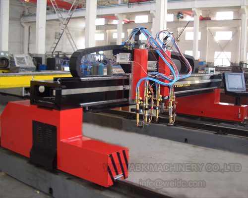
Joint preparation is where the fitter has the most effect and the least feedback. A bevel that is too narrow, a land that is too heavy, or a gap that changes along the seam will change penetration along the seam, no matter how steady the hand is. How that bevel was cut matters too. A flame-cut edge carries an oxide layer and a rougher land, and the oxide has to come off before welding or it ends up in the puddle as inclusions. A machined or cold-cut edge needs only cleaning.
Fit-up deserves the same attention as the torch. A gap that opens through the run pulls the puddle down and changes the current needed to hold the root, which is why a seam that welded cleanly at the start can fail at the far end.
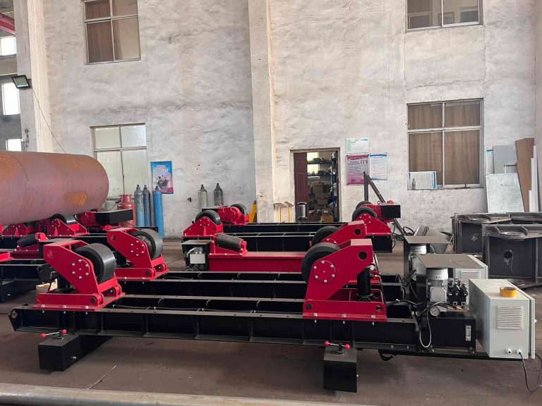
A gap that changes along the seam changes penetration with it, so alignment belongs in the diagnosis. <Fit-Up Rotator for Accurate Vessel Alignment & Stable Welding> covers how vessel sections are aligned and held before welding starts.
The check that settles it is a coupon. Weld a short section of the same joint, same alloy, same position, then bend it or cut and etch a cross-section. A bead that looks acceptable on the surface and fails on the bend has told you more than any setting change will.
Undercut, Crater Cracks, and Distortion From Heat Input
Undercut is a groove melted into the base metal at the toe of the weld that the filler never filled. It comes from arc force aimed at the sidewall with nothing left to refill it: current too high, arc too long, travel too fast, torch angle tipped too far toward one side, or a filler addition too small for the puddle the arc has created. Work angle and travel angle both matter here, and both drift without the operator noticing, especially when the joint has to be reached around.
Crater cracks form at the stop point, where the puddle contracts as it freezes. They are a termination problem rather than a welding problem. Taper the current down instead of breaking the arc, dab filler into the crater while the current falls, and keep the gas flowing until the crater has solidified. A crater left unfilled concentrates shrinkage stress at exactly the point where the section is thinnest.
Distortion belongs in the same group because it comes from the same input. Heat input, pass sequence, tacking, and restraint decide how much the part moves. Backstep welding, a balanced sequence, and fixtures that hold the joint in place all reduce it. Correcting distortion after the fact is possible with mechanical straightening, but that is recovery rather than control, and it cannot repair a joint that cracked while it was being pulled out of shape.
Cracks That Appear After the Weld Cools
A crack that appears hours or days after welding has a different cause from a crater crack. Three mechanisms account for most of them: solidification cracking while the weld metal is still partly liquid, hydrogen that entered the puddle and embrittled the metal as it diffused, and contamination that changed the chemistry of the joint.
Solidification cracking depends on the alloy, the filler, and how much the joint is restrained. Deep, narrow beads concentrate strain along the center line as the metal shrinks, and a joint clamped hard has nowhere to relieve it. On 6xxx aluminum, filler choice changes the solidification range: 4043 and 5356 are both used, and the choice trades crack resistance against strength and color match after anodizing. On stainless steel, the ferrite content of the weld metal and the heat input both affect crack sensitivity.
Hydrogen has a single practical answer, which is cleanliness. Moisture on the joint, oil from a machining operation, cutting fluid left on a bevel, condensation on a cold plate, and damp filler all put hydrogen into the arc. In carbon and low-alloy steels the result can be delayed cracking that appears long after the part has cooled, which is why drying and cleaning belong in the welding procedure rather than in housekeeping.
The cut edge is part of that cleanliness chain. Abrasive water jet cutting leaves a cold edge without a thermal oxide, but it also leaves abrasive residue and a wet surface that must be washed and dried before welding. Thermal cutting leaves an oxide that has to be ground back. Either method is workable; skipping the cleaning step is not.
One more source is easy to overlook on stainless: chloride. Cleaning solvents, some marking fluids, and rags used elsewhere in the shop can leave chlorides on the joint, and those both raise cracking risk and leave the finished weld open to corrosion. Use dedicated stainless brushes and clean, chloride-free solvents.
TIG Weld Troubleshooting Lookup for the Shop Floor
Use the table to pick the first check, not the final answer. Each row names the evidence that confirms the cause and the condition that sends you somewhere else.
| Symptom | Most likely cause | Check that confirms it | What points elsewhere |
|---|---|---|---|
| Scattered porosity along the bead | Air reaching the arc through the gas path | Pores clear after a flow check at the cup and a joint cleaned with fresh filler | Pores return in the same spot regardless of gas, so check base metal contamination |
| Gray or black tint on stainless | Shielding ran out while the metal was hot | Tint reduces after post-flow and draft control | Heavy tint with clean edges means heat input is too high |
| Tungsten balls unevenly or splits | Contamination or the wrong electrode for AC | A new electrode of the correct classification holds a stable ball | Repeated splitting points at the gas path or reversed polarity |
| Arc wanders and hums on aluminum | Electrode shape or balance setting | A reground electrode settles the arc | Wandering that follows the torch around the part points to magnetic interference |
| High crown with toes that do not wet in | Travel too fast or current too low | Bead flattens and toes blend as travel slows | Cold toes at higher current mean the bevel or land is too tight |
| Crack at the stop point only | No current taper or no filler at termination | Crack disappears with downslope and a filler dab | Cracking that runs past the crater is alloy, restraint, or hydrogen |
Five checks cover most of what the table points to. Confirm the work clamp and the ground path. Confirm polarity for the process and material. Measure gas flow at the cup with the torch in position. Replace and regrind the electrode lengthwise. Weld a coupon on scrap of the same alloy before returning to the production joint.
When the Limit Is the Position and Not the Torch
Some defects stop responding to technique because the technique is being asked to do something the position does not allow. Manual TIG depends on the operator holding arc length, torch angle, and travel speed inside a narrow band, and that band gets harder to hold as the joint moves overhead, as access tightens, or as the shift gets longer. A welder who runs a clean bead on a flat plate at waist height is not being careless when the same joint overhead starts showing incomplete fusion.
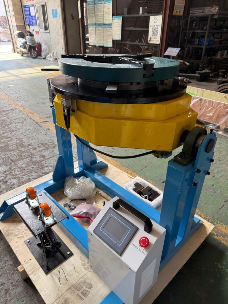
The response is to change what the operator has to control. Rotating the workpiece so the joint sits flat removes gravity from the problem and lets the same hand produce the same bead. Mechanizing the travel removes arc length from the problem, because the torch is held at a fixed distance by a structure rather than by a wrist. Neither change fixes a gas leak or a contaminated joint; a machine will reproduce a defect faster and more consistently than a person, so stabilize the manual process first.
Manual skill keeps arc length inside a narrow band, and that band is the first thing a mechanized system takes over. <Automatic Welding Centers Improve Production Efficiency & Weld Quality> covers how automated welding centers are configured to hold weld quality across a production run.
On a vessel or a long pipe spool, the seam is often longer than a comfortable reach, and the torch has to be carried on a structure.
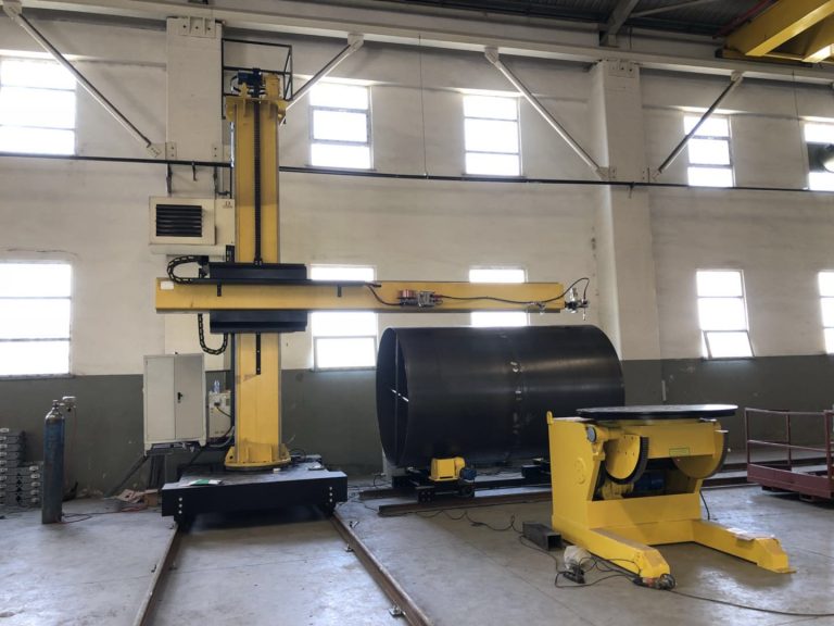
A seam longer than a comfortable reach turns arc length into a mechanical problem. <Column and Boom Manipulators for Large Vessel Precision Weldin> covers how those manipulators position the torch on large vessel work.
Mechanization also changes the defect set. Once a thick-plate seam moves to a submerged arc process on a tractor, porosity and fusion problems usually stop being about gas coverage at the torch and start being about flux handling, joint alignment, and travel stability.
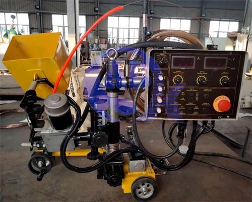
Large tanks add a second constraint, which is that the work is built where it stands. Shell courses are welded in position, the roof and the shell compete for access, and raising the structure changes what the welder can reach more than any torch adjustment can.

Tell Us the Defect and the Conditions Behind It
If a defect has survived the checks above, the next useful step is a second pair of eyes on the conditions rather than another setting. Send the base metal and thickness, the joint type and position, the shielding gas and how the flow was measured, the electrode classification, the machine settings, and a photograph of the bead and the tungsten. Add what you have already ruled out, because that saves more time than any single reading.
If the position or the volume is the real constraint, the same information supports a conversation about rotating the work or mechanizing the travel, and about what that would change in the defect pattern. Write to [email protected] or call +86 13616174307 at WUXI ABK MACHINERY CO., LTD, and attach the photographs to the first message.
FAQ
Why does my TIG weld turn gray or black on stainless steel?
Gray or black tint means the metal was still hot while oxygen could reach it. Check the gas path first: measure flow at the cup with the torch in position, confirm post-flow continues until the puddle stops glowing, and look for drafts from doors, fans, or an extraction arm. If the tint sits along the edges and the underside while the top of the bead stays light, shielding is the cause. If the whole bead is heavily tinted with a clean edge, heat input and travel speed are the cause, and more gas will not correct it.
How can I tell whether my gas flow is too high?
A cup that hisses, an arc that will not settle, and porosity that is worst directly under the torch are the usual signs. Excess flow creates turbulence at the cup mouth, and that turbulence pulls room air into the shield, which is why adding more gas can make the weld worse. Set the flow with a flowmeter at the cup outlet rather than at the regulator, then re-weld a coupon. If access is the real problem, a larger cup or a gas lens usually helps more than a higher flow rate.
Why does the tungsten ball unevenly or split on aluminum?
Uneven balling usually traces to contamination or to an electrode that is too small for the current. On AC the electrode carries part of the heat, so an undersized tungsten overheats, balls far beyond its diameter, and spreads the arc until penetration drops. A split tip is usually a contamination event, such as dipping into the puddle or touching the filler. Fit a zirconiated or lanthanated electrode of adequate size, regrind it lengthwise, and confirm the leads are not reversed before touching the balance setting.
Is porosity always a shielding gas problem?
No. Gas is the most common cause, but moisture, oil, cutting fluid, and oxide on the joint or the filler will produce the same pores behind a perfect shield. A wet tungsten, a damp electrode package, or a base metal surface wiped with a contaminated cloth can do it as well. The test is a clean coupon: fresh electrode, new filler from a sealed package, cleaned and dried plate. If porosity disappears there, the gas path was not the problem and the original joint was contaminated.
If you’re interested, check out these related articles:
Welding Manipulators for Storage Tanks: Girth and Seam Automation
Automatic Welding Centers Improve Production Efficiency & Weld Quality
Precision Positioning for Pipe and Shaft Welding Workpieces
Offshore Wind Tower Fabrication: Key Equipment and Main Challenges