How Does a Spot Welder Work? Resistance Welding Basics
Table of Contents
- What Happens During the Spot Welding Cycle
- The Main Parameters That Control Weld Quality
- How Material and Thickness Change the Weld Window
- Spot Welder Configurations and Production Controls
- Spot Welding vs Arc Welding for Thin Sheet Assemblies
- How to Make Spot Welds Repeatable
- Plan the Right Spot Welding Setup
- FAQ
- Can a spot welder weld aluminum?
- How thick of a stack can a spot welder weld?
- What causes weak spot welds?
- Does spot welding require shielding gas?
- Is a spot weld as strong as an arc weld?
- References
A spot welder joins overlapping metal sheets by passing a high current between two copper alloy electrodes while they press the sheets together. The electrical resistance at the sheet-to-sheet contact point heats the metal enough to form a small molten nugget, and the electrode force keeps that nugget under pressure until it solidifies. No filler metal, shielding gas, or open arc is required. That makes spot welding fast, localized, and easy to automate for thin sheet assemblies. It also means a spot welder only works when the joint allows current to pass from both sides and the workpiece can be squeezed between the electrodes.
What Happens During the Spot Welding Cycle
The spot welding process follows a defined sequence. First, the electrodes close and apply the preset force. This squeeze time removes gaps between the sheets and creates stable contact at the electrode tips and at the faying surfaces. Next, the controller switches on the welding current for a short interval. Heat generated at the highest-resistance point, the sheet-to-sheet interface, creates a molten nugget. Current then stops, but the electrodes remain closed during hold time to forge the solidifying metal. Finally, the electrodes retract and the part is indexed or removed [1].
The main sequence can be summarized this way:
- Squeeze: apply electrode force and establish contact.
- Weld: pass current through the sheet stack.
- Hold: keep force on the solidifying nugget.
- Off: open the electrodes and move the part.
Heat input follows the relationship Q = I² × R × t, where Q is heat, I is welding current, R is resistance, and t is time. This is why current changes have an outsized effect on heating: a small current increase raises heat by the square of the change. The machine combines current, time, and force into a weld schedule because no single setting controls nugget size alone.
The Main Parameters That Control Weld Quality
Four settings do most of the work: welding current, weld time, electrode force, and electrode contact area. They must be tuned together for the material and total stack thickness.
| Parameter | Main function | Lower than needed | Higher than needed |
|---|---|---|---|
| Welding current | Heats the interface to form the nugget | Undersized or absent nugget | Expulsion, deep indentation |
| Weld time | Controls how long heat is applied | Incomplete fusion | Overheating, distortion, rapid tip wear |
| Electrode force | Presses sheets together and contains molten metal | Arcing, expulsion, unstable resistance | Excessive indentation, reduced interface heating |
| Electrode tip diameter | Sets current density at the workpiece | Expulsion or surface damage | Shallow or weak nugget |
A narrow operating window exists between a weak weld and expulsion. Setups should be tested across a range of current and time, not only at one fixed value. Coated materials, poor fit-up, and electrode wear can shift that window during a production run.
How Material and Thickness Change the Weld Window
Material choice matters because the process depends on electrical and thermal resistance. Low-carbon steel is forgiving because it has moderate resistivity and lower thermal conductivity. Stainless steel has higher electrical resistivity and lower thermal conductivity, so it heats readily, but the schedule should still be proven for the specific grade. Aluminum is the opposite: its very low electrical resistance and high thermal conductivity pull heat away from the joint quickly, so the machine must deliver much higher current for a shorter time and the electrode faces need careful dressing.
Galvanized steel changes the contact surface. The zinc coating melts early and contaminates the electrode faces, which makes regular tip dressing part of the schedule rather than an optional housekeeping task. Dirty, oily, or heavily oxidized surfaces can also create inconsistent resistance and unstable weld quality.
Thickness is equally important. Spot welding prefers assemblies where the sheets are similar in thickness. When one sheet is much thicker, the thicker sheet acts as a heat sink while the thinner sheet can overheat. Engineers should check whether the material combination and thickness ratio fall within a proven weldability range instead of assuming a standard setting will transfer from another part.
Spot Welder Configurations and Production Controls
Spot welders come in three general machine forms. Rocker-arm units are common for smaller assemblies and lower force applications. Press-type machines provide heavier force and better electrode alignment for production work. Portable spot welding guns handle large or awkward parts where the part cannot easily move through a stationary machine.
The power source also changes behavior. Conventional AC transformers are widely used and low in complexity. Capacitor discharge units store energy and can produce short, high-current pulses with less total heat input. Medium-frequency inverter controls provide faster response and tighter current regulation, which is useful for high-strength steels and mixed material stacks. Electrode force is usually supplied by pneumatic cylinders, while servo force control is used where consistent force must be maintained over many weld cycles.
All of these systems need reliable cooling water for the transformer and electrode holders. A blocked water line will shorten tip life and can produce unstable welds even when the current setting is correct. Resistance welding equipment must also meet machine grounding and personnel protection requirements [2].
Spot Welding vs Arc Welding for Thin Sheet Assemblies
A spot welder and an arc welder solve different joint problems, so the comparison should start with joint design and production volume rather than process preference.
| Decision factor | Resistance spot welding | Arc welding such as MIG or TIG |
|---|---|---|
| Joint access | Requires access from both sides | Usually welds from one side |
| Filler metal | None | Consumable wire or filler rod |
| Heat input | Localized nugget, fast cycle | Wider heat-affected zone |
| Joint style | Mainly overlap or lap joints | Butt, fillet, lap, edge and corner joints |
| Material range | Best for thin sheet stacks | Broad range from thin sheet to heavy plate |
| Automation | Simple repetitive cycle, easy to robotize | More seam tracking and joint prep, but highly automatable |
Spot welding is not the right tool when the joint must be a continuous liquid-tight or gas-tight seam, when only one side is accessible, or when the total stack is too thick for a stable nugget. In those cases, seam welding, laser welding, or an arc process is usually more appropriate.
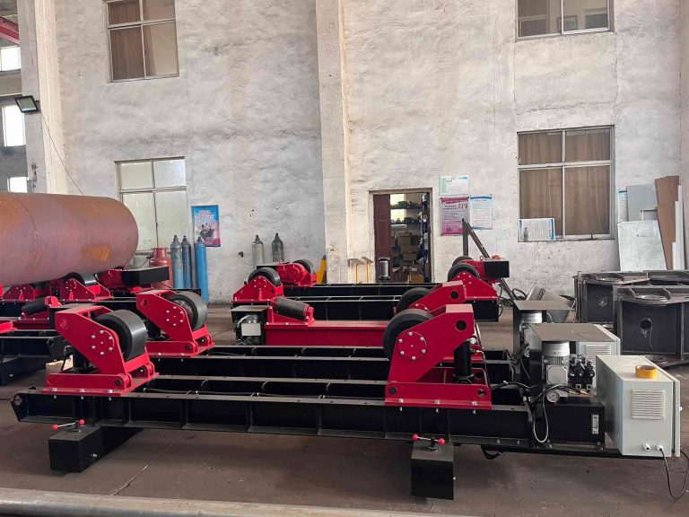
For larger cylindrical shells and long girth seams, companies generally pair welding manipulators and rotators with arc processes instead of trying to spot weld.
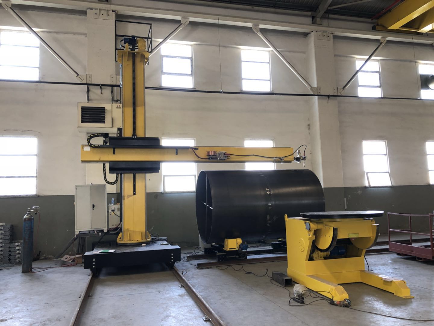
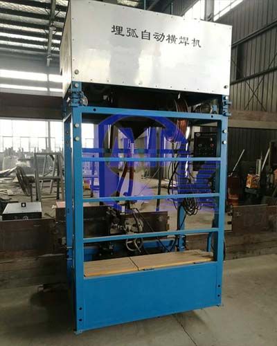
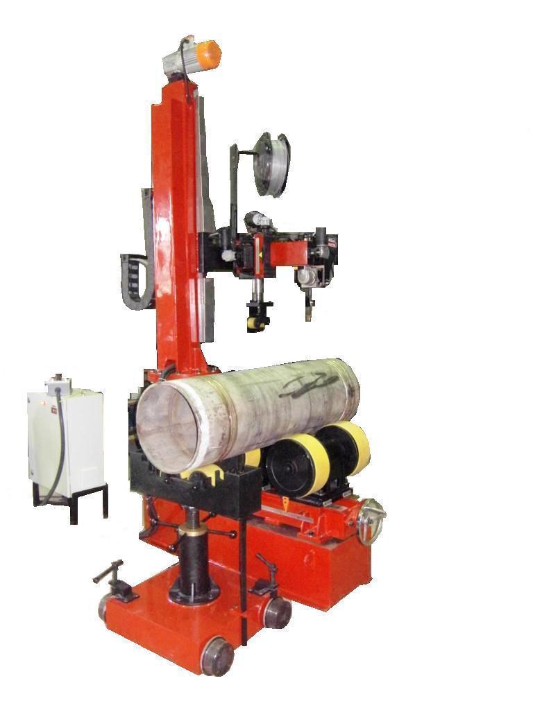
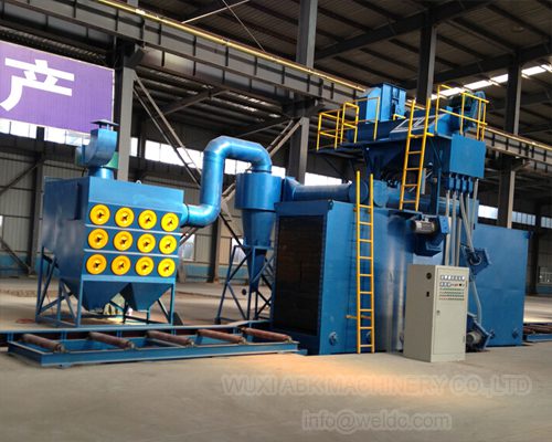
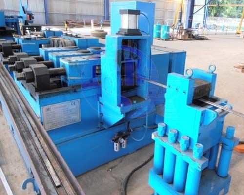
In a full production line, spot welding is only one station. Surface preparation and panel calibration remain separate steps that affect fit-up and joint consistency.
How to Make Spot Welds Repeatable
A stable spot welding process depends on more than the original schedule. Use matched and properly dressed electrode tips, and record the tip contact diameter during maintenance. Monitor water flow and electrode force because these drift gradually and can be missed during a busy shift.
For setup approval, use a peel or chisel test to expose the nugget. Visual inspection alone often misses an undersized nugget because the outside surface can look acceptable. For production, periodically destroy sample parts to confirm nugget diameter and failure location. Baseline destructive results should be compared with the process sheet, not with memory.
Also control the incoming material. Changes in sheet thickness, coating, oil, or surface condition can shift the resistance that the weld schedule depends on. A weld lobe test, where current and time are varied over a planned range, is a better way to establish an operating window than trying to hold a single maximum weld setting.
Plan the Right Spot Welding Setup
Before you specify or install a spot welding station, collect the material grade, total stack thickness, coating type, required weld spacing, and expected production rate. Those inputs define the current, force, and tip maintenance schedule that the cell must hold. If the application moves beyond simple flat sheet overlaps, the same production line may also need positioning, rotation, or long-seam welding equipment, and those systems should be planned together rather than bought piece by piece.
WUXI ABK MACHINERY CO., LTD. can review the proposed spot welding process as part of the wider welding and handling line, helping you avoid layout or equipment mismatches before installation. Contact us at [email protected] or +86 13616174307 with the part drawing and joint data for a practical configuration discussion.
FAQ
Can a spot welder weld aluminum?
Yes, but it requires a machine with enough output current and precise timing. Aluminum has low electrical resistance and high thermal conductivity, so the weld schedule must deliver much higher current for a shorter time than a comparable steel stack. Electrode tip care is also more demanding because aluminum oxide can contaminate the contact surface. A small spot welder set up for mild steel usually cannot make a reliable aluminum weld without a suitable power source and controls.
How thick of a stack can a spot welder weld?
Most spot welders are selected for thin sheet, often from a fraction of a millimeter up to a few millimeters per sheet depending on material and power. Exact capacity depends on the machine current, force, electrode geometry, and material conductivity. Thick or highly conductive stacks become difficult because heat dissipates before a nugget forms. The practical answer is to request a weldability check for the specific material and total thickness rather than relying on a single maximum thickness number.
What causes weak spot welds?
Common causes are low current, insufficient electrode force, oversized or worn electrode tips, short weld time, poor part fit-up, and dirty or coated surfaces that change contact resistance. Weak welds often look acceptable on the outside while the internal nugget is undersized. A teardown or peel test is more reliable than visual inspection because it shows the actual nugget diameter and whether the failure occurs in the base metal or along the joint.
Does spot welding require shielding gas?
No. Resistance spot welding does not use shielding gas, filler metal, or flux. The weld forms from resistance heating at the sheet interface while the electrodes apply force. Some specialized applications for reactive materials require special atmosphere or surface preparation, but ordinary mild steel and many coated steels are welded in normal air.
Is a spot weld as strong as an arc weld?
Strength depends on joint type, loading, and weld size. A spot weld can be very strong in shear, but a single spot does not create a continuous seam and performs differently under peel or fatigue loading. Designers usually compare required load per spot and spacing to the base material strength rather than treating one process as generally stronger. The appropriate test is a peel, tension-shear, or fatigue test on the actual joint configuration.
References
[1] Resistance Welder Manufacturers’ Association, “Resistance Welding Manual,” 4th ed., RWMA, 1989.
[2] U.S. Occupational Safety and Health Administration, “1910.254 – Resistance welding,” osha.gov. [Online]. Available: https://www.osha.gov/laws-regs/regulations/standardnumber/1910/1910.254
If you’re interested, check out these related articles:
Heavy-Duty Welding Rotators with 200 Ton Load Capacity
Welding Manipulators for Storage Tanks: Girth and Seam Automation
Storage Tank Fabrication: Core Equipment and Manufacturing Process
Fixed vs Adjustable Welding Positioners: How to Choose the Right Tool
Welding Equipment Factory Audits: Secure Quality Before Purchase