Orbital Welding: Scaling Automation for Heavy Pipe Fabrication
Table of Contents
- How Orbital Welding Works and Why It’s Different from Manual TIG
- Where Orbital Welding Fits Beyond Semiconductor and Pharma
- Integrating Orbital Welding with Heavy Pipe Positioning Equipment
- Key Factors for Successful Orbital Welding on Industrial Piping
- Evaluating Orbital Welding Equipment for Your Shop
- Common Questions About Orbital Welding in Heavy Fabrication
Orbital welding is the most repeatable method for joining pipe and tube in automated fabrication, but its reputation as a cleanroom-only technology misses a larger opportunity. In heavy industries like pressure vessel manufacturing, boiler fabrication, and wind tower piping, the same precision that ensures zero-defect welds in semiconductor lines can slash rework rates and speed up code-compliant production — provided the setup includes the right pipe handling equipment. I’ve seen shops double their output on scheduled pipe spools by integrating orbital welding systems with heavy positioning machines, and this guide explains how to do the same, from weld head selection to full shop layout.
How Orbital Welding Works and Why It’s Different from Manual TIG
Orbital welding automates the entire arc welding process around a stationary tube or pipe. A weld head clamps onto the workpiece, a tungsten electrode rotates 360 degrees inside an enclosed chamber, and an arc is struck and controlled by a programmable power supply. The system regulates current, travel speed, arc voltage, and wire feed (when filler metal is needed) through pre-set weld schedules. For heavy-wall pipe above 2 inches, water-cooled weld heads are common, and the power supply must deliver enough amperage to achieve full penetration.
Manual TIG welding, by contrast, depends entirely on the welder’s hand speed, torch angle, and filler rod feeding consistency. For a 6-inch schedule-80 butt weld in a horizontal fixed position, even an experienced TIG welder will fatigue, and small variations in travel speed create inconsistent penetration. Orbital welding eliminates that variability. The same weld schedule can be repeated across hundreds of identical joints, and the data logger records every parameter for quality documentation. This repeatability is why orbital welding is trusted for ASME and EN code work, not just cleanroom tube welding.
Where Orbital Welding Fits Beyond Semiconductor and Pharma
Orbital welding has long been the standard for high-purity tube installations in semiconductor fabs and pharmaceutical process lines, where internal surface finish and zero contamination are critical. But the technology is equally effective on industrial piping systems that demand full-penetration, low-defect welds but operate in far harsher environments.
I’ve specified orbital welding for boiler tube panels, economizer connections, and pressure vessel nozzle joints, where tube diameters range from 2 inches to 6 inches and wall schedules run from 10 to 80. In wind tower manufacturing, internal hydraulic and cooling lines use orbital welding to avoid leaks in hard-to-access locations, and in oil and gas module fabrication, orbital systems are applied to process piping that must pass radiography. The common thread is a requirement for consistent, documented weld quality on repetitive joints. Fabrication shops that move beyond the cleanroom mindset and apply orbital welding to these heavier applications often see a measurable drop in repair rate, sometimes by 30% or more on multi-joint projects, because the process reduces the human variables that cause most defects.
Integrating Orbital Welding with Heavy Pipe Positioning Equipment
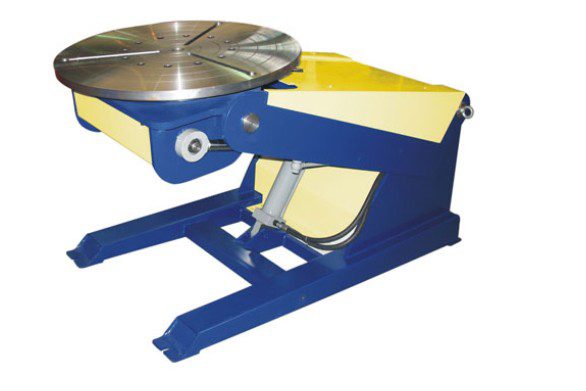
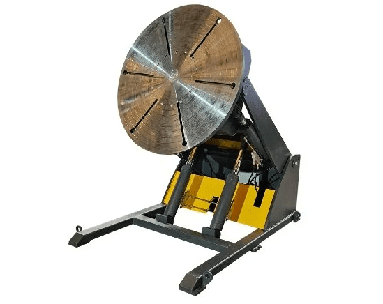
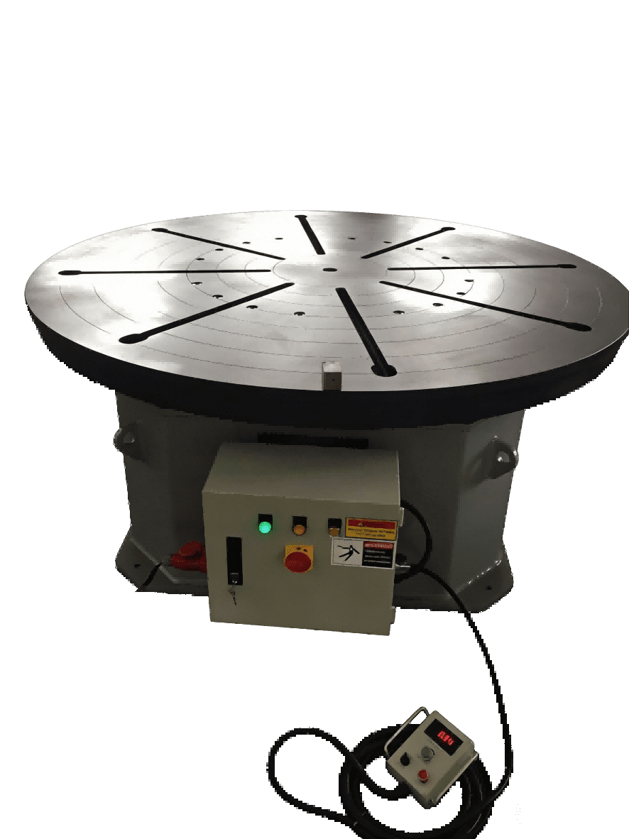
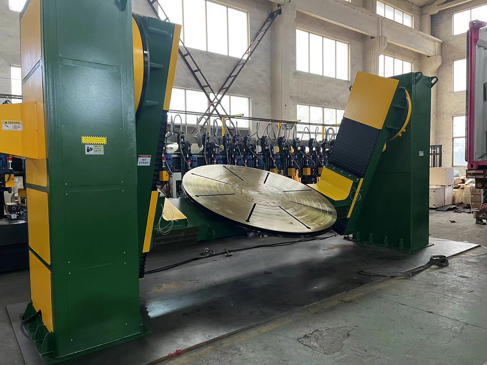
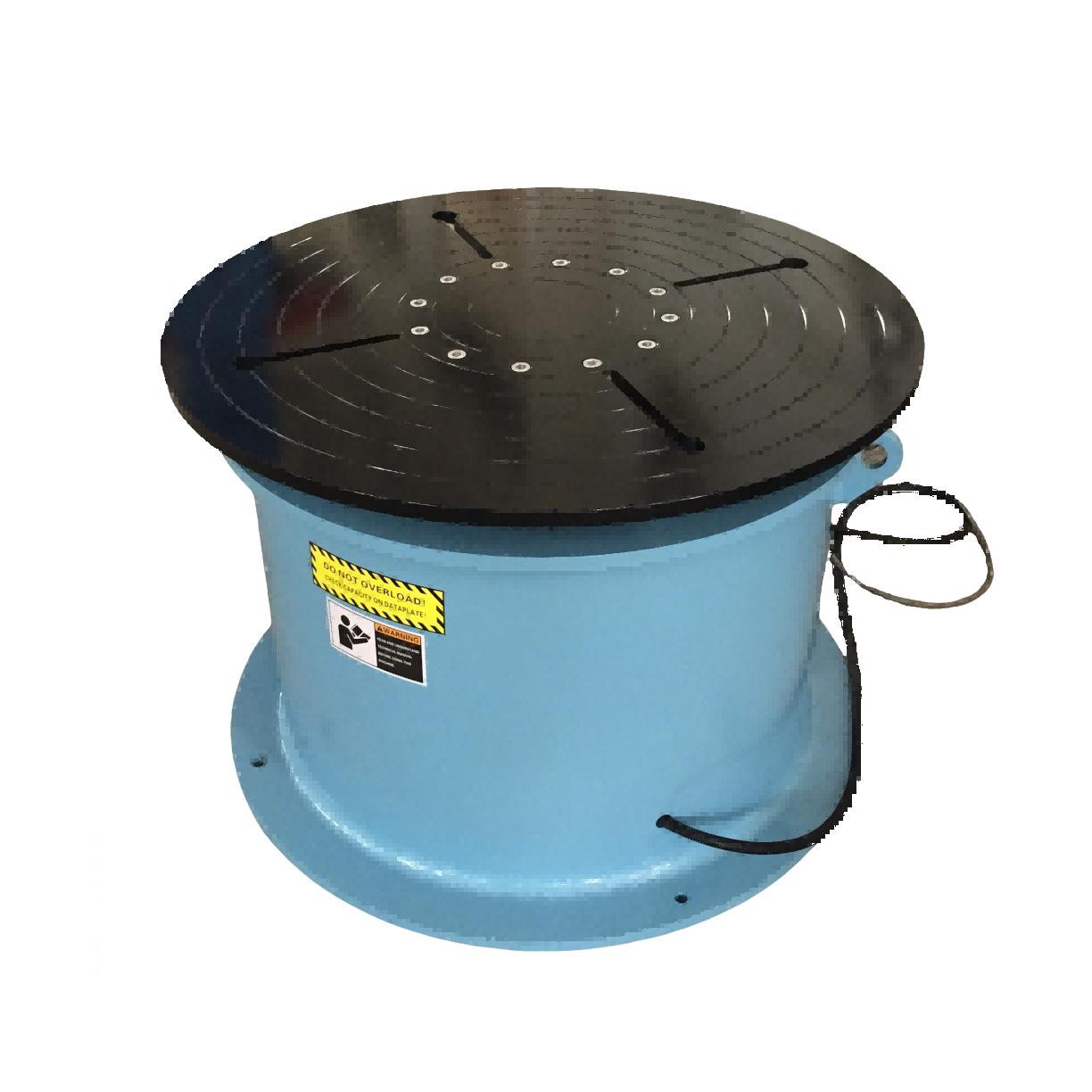
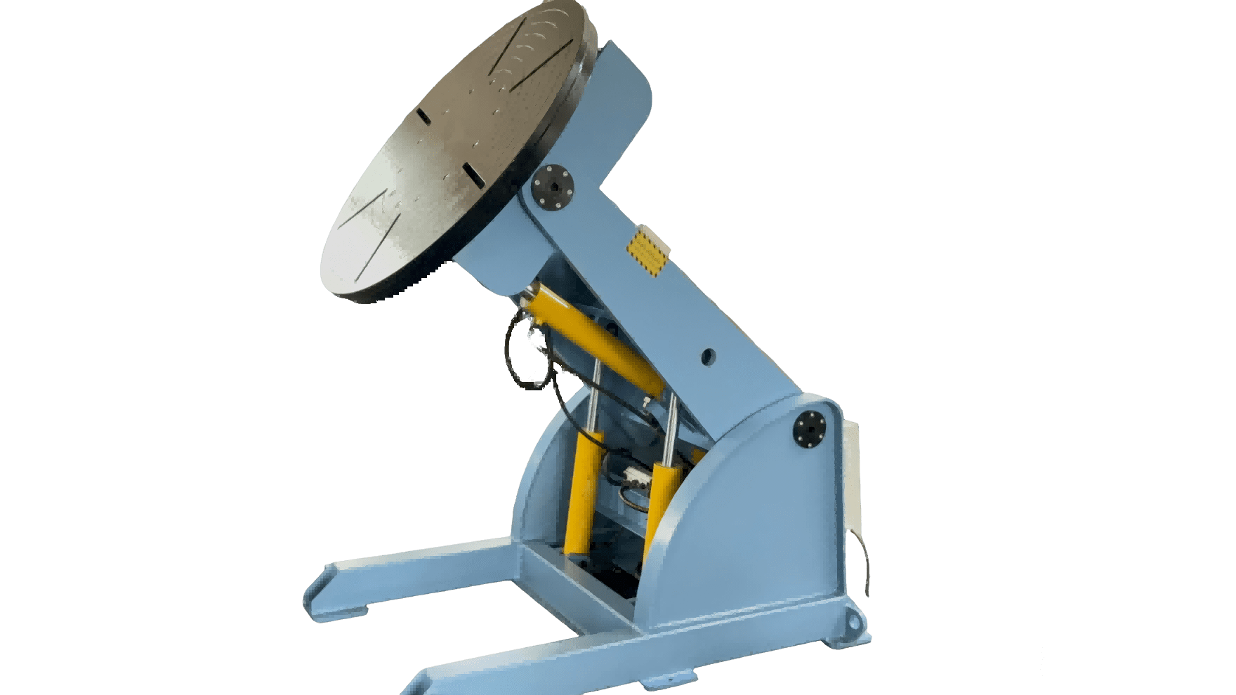
Clamping an orbital weld head onto a 6-inch schedule-80 pipe that is suspended by a crane introduces movement, misalignment, and a safety risk. The weld head is only one part of the system; the rest is getting the workpiece into a stable position and keeping it there throughout the weld cycle. For heavy fabrication, that means integrating orbital welding with industrial positioning machines: welding rotators to support and rotate long pipe sections, welding positioners to orient fittings and flanges, and column-and-boom manipulators to position the weld head precisely over the seam.
A self-aligning welding rotator, for example, can handle pipe diameters from 2 to 8 inches and rotate at a controlled speed while the orbital head remains stationary. A head-and-tail welding positioner can hold a complex assembly, like a pressure vessel nozzle with a flange, at the exact angle needed. This combination is not unusual in automated pipe spool shops, where a single operator can oversee multiple stations. If your project involves heavy-wall pipe with stringent code requirements, confirming the positioning equipment’s capacity and precision is just as important as selecting the weld head — reach out at [email protected] to discuss your application and I’ll help you match the tooling to your pipe range.
Before tacking, a fit-up rotator brings the pipe ends into alignment and holds them for orbital tack welds. Adjustable welding rotators with variable frequency drives can be tuned to match the orbital weld speed, ensuring smooth rotation without stutter that could disturb the arc. The interface between the positioner’s control system and the orbital power supply can be as simple as a start signal, or as integrated as a coordinated multi-axis motion system for complex weld sequences. (See our guide on Welding Positioner Selection for Pressure Vessels for more on capacity and configuration rules.)
Key Factors for Successful Orbital Welding on Industrial Piping
Even with a perfectly programmed weld schedule, orbital welding is not a push-button process. The four factors that most often determine success on industrial piping are:
- Fit-up quality. A consistent root gap is critical. For orbital welding without filler wire, the gap must match the electrode oscillation width within a few thousandths of an inch. For welding with filler wire, the gap can be slightly wider, but any variation will show as inconsistent reinforcement.
- Purging and shielding gas control. Back purging with argon displaces oxygen inside the pipe to prevent sugaring of the root pass. The purge time depends on pipe volume, so larger diameters require longer pre-purge. Flowmeters and oxygen sensors help ensure the purge is complete before the arc starts.
- Tack weld placement and sequence. For heavy-wall pipe, four equally spaced tack welds help resist the shrinkage stress that can close the root opening mid-weld. The tack welds should be performed using the same orbital program (or a dedicated tack program) and blended into the final weld.
- Weld schedule development. The orbital power supply needs a schedule that sets amperage, rotational speed, wire feed speed (if used), and oscillation width. Developing that schedule for a given pipe diameter and wall thickness requires test coupons and destructive or radiographic testing, but once validated, the schedule can be stored and reused indefinitely.
Shops that add orbital welding often start with one or two standard pipe schedules and expand from there. I always recommend running a procedure qualification record (PQR) per the applicable code before production welding, because even small differences in material or fit-up can affect the outcome.
Evaluating Orbital Welding Equipment for Your Shop
When investing in orbital welding for heavy pipe fabrication, the power supply and weld head are the obvious starting points, but the full system and support plan matter just as much.
The power supply should offer multiple weld schedule storage, real-time data logging, and the ability to export weld parameters for quality control records. For heavy industrial use, look for a power supply with at least 300 ampere output capacity and a water-cooler interface if you plan to run continuous production. The weld head must be sized for your maximum pipe diameter and have the clamping force to stay fixed during rotation. For schedule-80 and thicker walls, closed-loop arc voltage control (AVC) is essential to maintain constant arc length as the electrode orbits the pipe.
Equally important is the positioning machinery that surrounds the weld head. The rotators, positioners, and manipulators must have load capacities, speed ranges, and control interfaces that match the welding process. I advise buyers to request a full system demonstration, or at minimum a detailed factory acceptance test plan. (Our guide on Factory Audits for Welding Equipment outlines what to verify before signing.) In remote locations or for export orders, spare parts availability, qualified training, and clear installation documentation become deal-breakers. I’ve seen too many projects stall because a single positioner control board was not included in the initial order, so I always recommend discussing the spares package upfront.
Common Questions About Orbital Welding in Heavy Fabrication
What is the smallest pipe diameter that still justifies orbital welding in heavy industry?
Orbital weld heads typically start at a minimum diameter of around 1/2 inch. In heavy fabrication, the economic threshold is usually around 2 inches. Below that, the volume of small-diameter tube joints in industrial settings is often too low to offset the equipment cost. But if you are fabricating dozens of identical instrument tube assemblies per shift, even a small head pays back quickly through repeatability and reduced rework.
Can orbital welding handle thick-wall pipe for process pressure vessels?
Yes, with the right weld head and power supply, multi-pass orbital welding is possible on pipe walls up to schedule 80 and even schedule 160. The first pass is typically an autogenous melt run, followed by filler-wire passes with a wire feed attachment. The schedule must account for interpass cooling and travel speed adjustments, but once developed, it can be repeated consistently without operator fatigue.
How does the cost of orbital welding compare to manual TIG for a shop doing repetitive pipe spools?
The initial capital outlay is higher — a complete orbital system with weld head, power supply, and positioner can cost several times that of a manual TIG setup. But the labor savings, lower repair rate, and faster cycle time often deliver a return on investment in 12 to 18 months for shops producing tens or hundreds of identical joints per week. The biggest financial gain comes from reliability: a weld that passes radiography on the first attempt eliminates the cost of grinding, re-welding, and re-inspecting.
What about ground connection and cable handling on rotating systems?
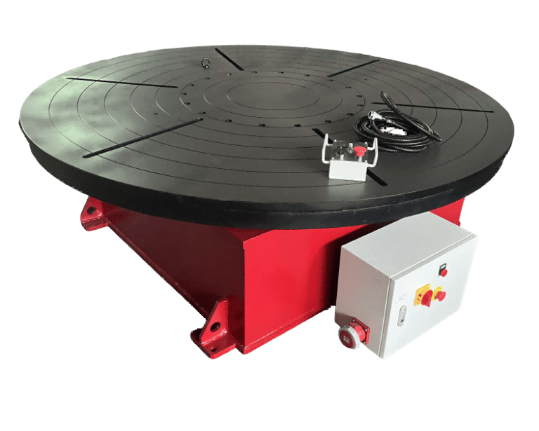
On a rotary positioner, the grounding must be continuous and clean to avoid arc instability. This usually means a slip ring or a copper grounding shoe contacting the workpiece. Cable strain relief and organized routing prevent the weld head cables from tangling or chafing during rotation. A well-designed installation includes a cable track or a rotating union for power, gas, and data lines, especially on head-and-tail positioners.
If your shop is planning to add orbital welding to an existing automated line, sharing your pipe diameter range and production targets with our team helps identify the right positioning solution before committing capital. We can review your layout and recommend an equipment package that integrates smoothly with your current workflow.
For heavy fabricators looking to take the next step toward consistent, code-quality pipe welding, the key is not just the orbital weld head but the entire positioning and automation system. I’ve seen how properly integrated systems reduce rework and increase throughput in demanding industrial environments. Send your project details, including pipe sizes and required welding standards, to [email protected] or call +86 13616174307. We’ll review your layout and recommend an equipment package that matches your production scale.
If you’re interested, check out these related articles:
Heavy-Duty Welding Rotators with 200 Ton Load Capacity
Wind Tower Welding Lines: Designing for Peak Production
Column and Boom Manipulators for Large Vessel Precision Weldin
H-Beam Assembly: Automated Web and Flange Fit-Up Precision