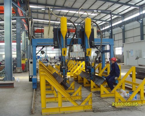
Head and Tail Welding Positioners Designed for Long, Heavy Fabrication Workpieces
Table of Contents
- Head and Tail Positioners Provide Stable Support for Long Workpieces
- Load Capacity and Torque Define Heavy-Duty Performance
- How Do I Calculate the Required Torque?
- Why Moment Load Limits Matter More Than Static Weight
- Head and Tail Positioner Alignment Prevents Deflection and Weld Defects
- Custom Head and Tail Positioner Configurations for Long, Heavy Workpieces
- Automated Systems Integrate Positioners with Welding Manipulators
- Common Setup Errors Compromise Accuracy and Safety
- Common Questions About Head and Tail Welding Positioners
- What’s the difference between a head and tail positioner and a conventional welding positioner?
- Can a head and tail positioner handle out-of-round or non-cylindrical parts?
- How do I choose between a head and tail positioner and a 3-axis positioner?
- What maintenance keeps a head and tail positioner accurate over time?
- Can I retrofit an existing welding cell with a head and tail positioner?
In heavy fabrication shops, rotating a 15-meter wind tower section or a multi-ton pressure vessel for welding demands more than just lifting capacity. The workpiece must turn smoothly and hold position without sagging or losing alignment. A head and tail welding positioner distributes the weight between two synchronized supports, making it possible to weld long, heavy workpieces with consistent precision. But from my experience supporting projects worldwide, I’ve seen that selecting the right positioner isn’t just about matching the load rating. It’s about aligning drive power, rigidity, and setup practices to the real-world shape and length of the part. Before you spec a head and tail positioner for your heavy fabrications, a few practical considerations can save rework and downtime later.
Head and Tail Positioners Provide Stable Support for Long Workpieces
A conventional welding positioner uses a single rotary table to tilt and rotate the workpiece. That works well for compact parts, but a long, heavy assembly like a cylindrical storage tank or a wind tower section tends to overhang and deflect under its own weight. A head and tail positioner eliminates this problem by supporting the workpiece at both ends. The headstock, which contains the drive motor and gearbox, clamps one end of the part and provides rotational torque. The tailstock, mounted on a linear rail or adjustable base, supports the opposite end and can be moved to accommodate different workpiece lengths.
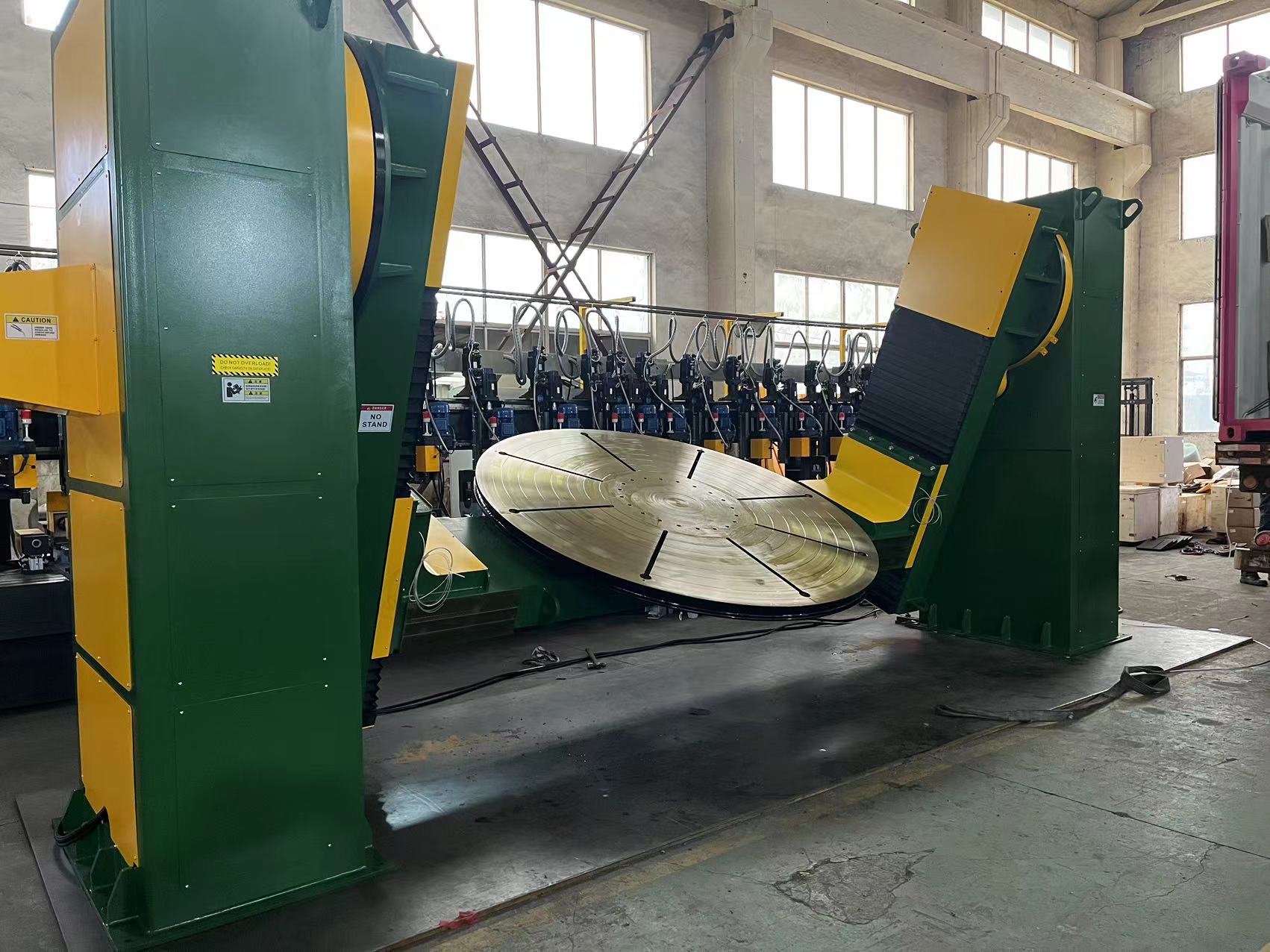
For long workpieces, the distance between the two supports becomes a critical factor. The longer the span, the more the workpiece acts as a beam, and any misalignment between the headstock and tailstock centerlines translates directly into wobble and weld path deviation. In practice, we at ABOKE always verify alignment with a dial indicator before production runs, especially when the workpiece length exceeds three meters. Even a small offset at the tailstock can cause a visible oscillation at the weld torch, leading to inconsistent bead width and increased spatter.
Load Capacity and Torque Define Heavy-Duty Performance
Load capacity is the first number engineers check, but for long workpieces, torque at the headstock drive matters just as much. A positioner rated for 10 tons may struggle to start and stop a 10-ton workpiece if the center of gravity is far from the faceplate or if the workpiece has a large moment of inertia. The drive must deliver enough torque to accelerate the mass smoothly and hold position accurately during welding, including during intermittent stops for tacking or inspection.
When specifying a head and tail positioner, look beyond the static load rating and request the torque curve and speed range. For workpiece weights above 20 tons, hydraulic motors or high-torque AC servo drives often become necessary. We have configured positioners with dual drives on the headstock for ultra-heavy sections, where a single motor would be oversized and inefficient.
| Positioner Capacity | Typical Torque Range | Max Workpiece Length | Recommended Drive Type |
|---|---|---|---|
| Up to 5 tons | 500 to 1,500 Nm | 3 to 5 m | AC motor with VFD |
| 5 to 20 tons | 1,500 to 6,000 Nm | 5 to 10 m | Servo motor with planetary gearbox |
| 20 to 50 tons | 6,000 to 20,000 Nm | 10 to 20 m | Hydraulic or high-torque servo |
| Custom over 50 tons | Engineered to order | 20+ m | Multiple drive or hydraulic |
The values above reflect common configurations, but every application has quirks. A workpiece with an uneven weight distribution, such as a vessel with attached nozzles, may require a higher torque margin to avoid stalling at certain rotation angles. If your workpiece has unusual geometry, we can simulate the load moments and specify a drive package that covers the worst-case angle.
How Do I Calculate the Required Torque?
Calculating the required torque starts with the workpiece’s moment of inertia and the desired acceleration. A rough method: multiply the workpiece weight by the distance from the rotation axis to its center of gravity. Add a 25 to 50 percent safety factor for friction and dynamic loads. For precise selection, provide the CAD data or weight distribution profile, and we can run the numbers.
Why Moment Load Limits Matter More Than Static Weight
Static weight tells only part of the story. A heavy workpiece with its center of mass far from the faceplate generates an overturning moment that the headstock bearings and base frame must resist. Ignoring this can lead to bearing failure or frame fatigue. Always check the positioner’s moment load rating, not just its tonnage, when the part extends more than a meter beyond the chuck.
Head and Tail Positioner Alignment Prevents Deflection and Weld Defects
On paper, the headstock and tailstock centers should be coaxial to within 0.1 mm. In the real world, foundation settling, thermal expansion, and wear can shift that alignment. For a long workpiece, a 0.5 mm offset at the tailstock creates a 1.5 mm radial runout at the weld joint six meters away, enough to cause lack of fusion or uneven penetration.
Step-by-step alignment procedure:
1. Mount a precision test bar or the actual workpiece between centers.
2. Attach a dial indicator to the headstock chuck and rotate the spindle by hand, measuring runout at the tailstock end.
3. Adjust the tailstock horizontal and vertical jackscrews until runout is within tolerance.
4. Recheck after the first few welding passes, as thermal expansion can shift alignment.
I recall a pressure vessel project where a misaligned tailstock caused a persistent offset in the girth weld. The operator kept adjusting the welding torch to compensate, which only created a varying root gap. After realigning the tailstock, the issue disappeared. That experience reinforced a simple rule: if the positioner isn’t true, no amount of welder skill can fix the problem.
Custom Head and Tail Positioner Configurations for Long, Heavy Workpieces
Standard catalog positioners cover a useful range, but many fabrication shops need something beyond the brochure. When workpiece lengths exceed 10 meters or weights surpass 50 tons, custom engineering becomes cost-effective. We often extend the tailstock rail system, add intermediate roller supports to prevent sag, or specify self-aligning tailstocks that pivot slightly to accommodate workpiece runout without binding.
For extremely long sections like 30-meter monopile segments, a single head and tail positioner may not be enough. In those cases, we split the support into multiple synchronized positioner sets, with the headstock acting as master and the tailstocks and intermediate rollers as slaves, all tied to a central PLC. This configuration maintains uniform rotation speed across the entire length.
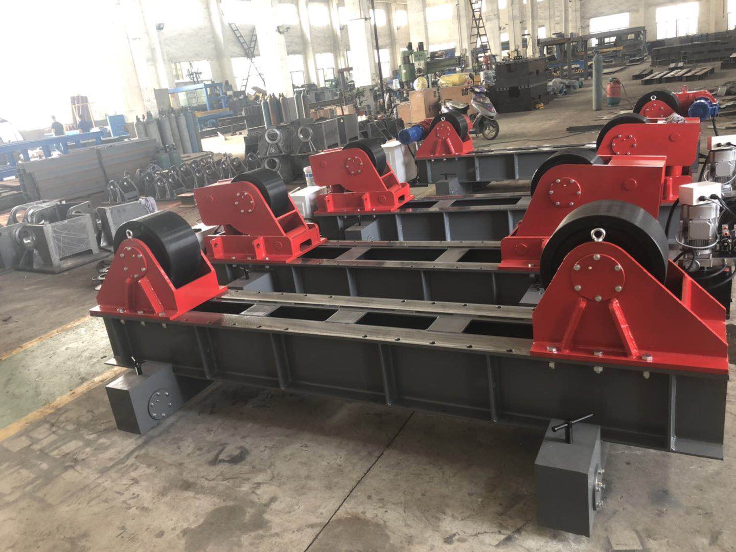
If your part dimensions push the limits of standard equipment, contact us at [email protected]. We routinely design positioners with extended beds, higher load capacities, and custom chucks to grip non-standard profiles. Let us know your workpiece length, diameter, and weight, and we’ll propose a tailored solution.
Automated Systems Integrate Positioners with Welding Manipulators
A head and tail positioner rarely works alone. In automated production, it pairs with a column and boom manipulator or a robotic arm to form a complete welding station. The positioner rotates the workpiece, while the manipulator moves the welding head along the joint. Coordination between the two axes determines the quality of the weld.
Synchronization is usually handled by a PLC that controls both the positioner rotation and the manipulator travel. The PLC can maintain a constant welding speed regardless of part diameter, ensuring consistent heat input. For submerged arc welding (SAW), this integration becomes especially important because travel speed directly affects flux coverage and slag removal.
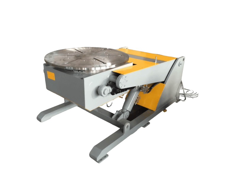
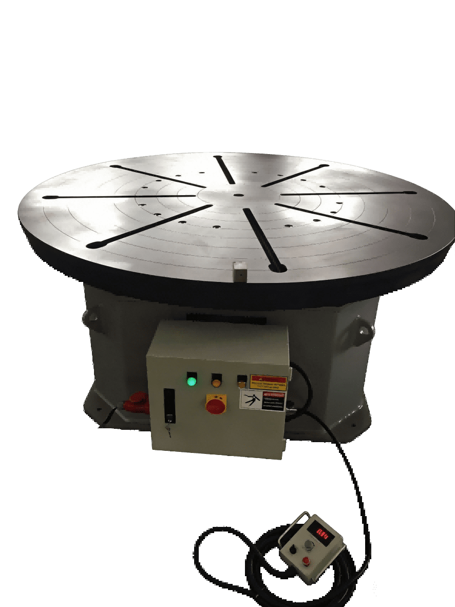
We have integrated head and tail positioners with manipulators ranging from 2×2 meters up to 10×10 meters, with the ability to store weld recipes for different workpiece families. If you are planning an automated welding line, reach out early in the design phase. Aligning the positioner, manipulator, and safety systems before the equipment order avoids costly field modifications. For parts that are shorter and more compact, a rotary welding turntable like the 20-ton model shown below can offer a simpler alternative.
Common Setup Errors Compromise Accuracy and Safety
Even a well-engineered positioner can deliver poor results if the setup is rushed. The following errors show up repeatedly in real-world installations, and they are usually avoidable.
Rigid base, not just level. A head and tail positioner transfers significant torque into the floor. Bolting it to a level surface isn’t enough; the foundation must be rigid enough to resist twisting. We recommend a reinforced concrete pad with embedded anchor bolts, especially for loads above 20 tons.
Ignoring dynamic braking. When the drive stops, the momentum of a heavy workpiece can cause it to coast. A positioner without adequate braking or a servo drive with precise positioning may overshoot, throwing off the weld seam. Verify that the brake can hold 150 percent of the full-load torque.
Neglecting out-of-round workpieces. A workpiece that isn’t perfectly round will cause the tailstock center to shift cyclically. Use a self-aligning tailstock or a floating center to accommodate this, otherwise the positioner’s bearings will suffer uneven loading.
Skipping regular maintenance. Dust, weld spatter, and scale can accumulate on guide rails and lead screws, increasing friction and wear. A weekly cleaning and lubrication schedule, along with quarterly alignment checks, keeps the positioner accurate over years of heavy use.
Reliable positioning is the foundation of every heavy fabrication project. A head and tail welding positioner, correctly selected and set up for your longest, heaviest workpieces, eliminates sag and misalignment at the source. At WUXI ABOKE MACHINERY, we combine over 20 years of manufacturing experience with practical field knowledge to engineer positioners that match your production reality. Send your workpiece dimensions, weight, and any special requirements to [email protected] or call +86 13616174307. We’ll help you choose a configuration that fits your shop and your quality standards.
Common Questions About Head and Tail Welding Positioners
What’s the difference between a head and tail positioner and a conventional welding positioner?
Conventional positioners use a single rotary table, often tiltable, for smaller parts that can be supported by a single chuck or faceplate. A head and tail positioner uses two separate units, one drive end and one support end, to hold long workpieces that would otherwise overhang and deflect. The head and tail design distributes the weight and maintains alignment across the full length, making it the go-to choice for pipes, shafts, vessels, and structural profiles over 3 meters.
Can a head and tail positioner handle out-of-round or non-cylindrical parts?
Yes, with the right fixturing. If the workpiece is slightly out of round, a self-aligning tailstock or a live center can compensate for the variation without binding. For square or rectangular profiles, we can supply custom chucks or V-blocks that grip the part securely while allowing rotation. The tailstock may need additional adjustability to accommodate non-uniform shapes.
How do I choose between a head and tail positioner and a 3-axis positioner?
A 3-axis positioner adds a tilt axis, which is beneficial for parts that require complex orientation, such as weldments with multiple joint angles. A head and tail positioner is typically better for long, heavy parts that need only rotation, because the two-point support provides greater stability and load capacity. If your part is long and also needs tilting, we can design a head and tail system with a tilting tailstock, but that’s a custom solution.
What maintenance keeps a head and tail positioner accurate over time?
Regular maintenance includes cleaning rails and lead screws of weld spatter and dust, lubricating moving parts weekly, checking alignment monthly (especially after heavy use), and inspecting electrical connections and brake function quarterly. Bearings and gearboxes should be monitored for abnormal noise or heat. Most accuracy drift comes from neglected alignment checks.
Can I retrofit an existing welding cell with a head and tail positioner?
It depends on your current manipulator travel range, control system, and floor space. We have retrofitted many systems by adding a head and tail positioner alongside an existing column and boom manipulator, synchronizing them through the PLC. If you’re considering a retrofit, share your current layout and part envelope. We can often suggest a plan that fits without major floor modifications.
If you’re interested, check out these related articles:
Evaluate ROI of Welding Automation Business Investment
Fit-Up Rotator for Accurate Vessel Alignment & Stable Welding
Storage Tank Fabrication: Core Equipment and Manufacturing Process
Automatic Girth Welding Machines: Boost Efficiency for Pipeline Projects
Automatic Welding Centers Improve Production Efficiency & Weld Quality