.035 Hardwire Settings for MIG: Amps, Voltage, Setup Chart
Table of Contents
- What .035 Hardwire Settings Work for Mild Steel?
- How Do You Set Voltage and Wire Feed Speed Correctly?
- When Should You Push .035 Hardwire Settings Into Spray Transfer?
- Why Does .035 Hardwire Burn Back or Porosity?
- What Stops Burn Back on Thin Gauge?
- Why Does Porosity Show Up Even With Correct Feeds and Speeds?
- Having Trouble With .035 Hardwire Settings on Your Production Line?
- What Do Welders Ask About .035 Hardwire Settings?
- Does .035 Hardwire Need a Special Drive Roll?
- Can I Run .035 Hardwire on a 115 Volt MIG Machine?
- Why Does My .035 Hardwire Weld Leave Brown Glass Islands and Soot?
- Is .035 Hardwire Worth Changing From .030 for 1/8 Inch Plate?
Nearly every .035 hardwire settings problem I find on shop floors begins the same way: the welder treats solid MIG wire as if it should respond like flux core. The two processes do not share the same voltage window or stick-out tolerance. With ER70S-6 hardwire and a 75/25 argon-CO2 shield, the settings are predictable, but only when voltage, wire feed speed, and travel speed are corrected in that order. If the puddle is pushing, cracking, or burning through, the chart below will usually expose which parameter moved first.
What .035 Hardwire Settings Work for Mild Steel?
On clean carbon steel plate without mill scale, I use the ranges below as the starting point for ER70S-6 with 0.035 inch hardwire, a 3/8 to 1/2 inch stick-out, and a 75/25 argon-CO2 gas shield at 20 cubic feet per hour. The table is not a substitute for puddle reading, but it stops most cold lap and burn-through complaints before the first arc.
| Material Thickness | Wire Feed Speed (ipm) | Voltage (V) | Amperage Range | Gas Flow (CFH) |
|---|---|---|---|---|
| 18 gauge, 0.047 in | 130 to 160 | 15 to 17 | 60 to 90 | 20 |
| 1/8 in | 250 to 300 | 18 to 20 | 130 to 160 | 20 |
| 3/16 in | 320 to 380 | 20 to 23 | 170 to 210 | 20 |
| 1/4 in | 400 to 470 | 23 to 26 | 210 to 250 | 20 |
| 3/8 in | 480 to 580 | 26 to 29 | 250 to 310 | 25 |
One correction I make on production cells often is the relationship between voltage and wire feed speed. If you raise wire feed from 280 to 340 ipm without adding voltage, the arc turns harsh and the puddle becomes narrow. Add about 1 volt for every 40 to 50 ipm increase above 250 ipm, then refine by sound. A clean short circuit arc sounds like bacon frying, not intermittent snapping.
How Do You Set Voltage and Wire Feed Speed Correctly?
The order matters more than the exact numbers. I set voltage first for the base thickness, then bring wire feed speed up until deposition matches travel speed. A welder who sets wire speed first ends up chasing the puddle with the voltage knob, and that is where most undercut and cold lap starts.
- Set voltage to the chart value for the material thickness and leave it.
- Set wire feed speed at the lower end of the range.
- Start the arc on scrap, not on the part, and listen for a steady short circuit buzz.
- Increase wire feed speed in small steps until the bead wets into the toes without pushing ahead of the puddle.
- If the arc becomes stiff or the gun pushes back, add voltage in half volt increments.
With .035 hardwire, stick-out changes the real arc energy even when the display voltage stays the same. A 3/8 to 1/2 inch stick-out is normal for short circuit work. At 5/8 inch, the wire preheats less and the puddle runs colder. I have watched two identical machines produce different weld profiles because one operator held the nozzle one inch from the joint.
When Should You Push .035 Hardwire Settings Into Spray Transfer?
Most general fabrication stays in short circuit. Spray transfer with .035 hardwire needs roughly 27 to 30 volts and 450 to 600 ipm with a 90/10 argon-CO2 or 98/2 argon-oxygen shield, not the 75/25 mix used for short circuit. I use spray only on 5/16 inch and thicker carbon steel in flat and horizontal positions because the puddle becomes too fluid for vertical or overhead work.
At these settings, the arc is nearly silent and the bead appearance changes completely. If the power source cannot hold 28 volts under load, do not force the wire speed higher; the result is spatter, not spray.
If your line welds the same fillet or lap joint all day, it is worth confirming the upper power limit and gas blend before you rewrite a procedure. Send your material thickness and current gas mix to [email protected] and I will check whether the short circuit numbers you are copying are actually the right starting point.
Why Does .035 Hardwire Burn Back or Porosity?
Burn back and porosity are the two failure signs I treat as machine checking signals. Both can appear while the settings on the panel look correct.
What Stops Burn Back on Thin Gauge?
Burn back on 18 gauge usually means the wire feed speed is too low for the selected voltage, or the contact tip is worn. Lower the voltage to 15.5 V and set wire speed near 150 ipm. If the wire still pulses back, reduce drive roll tension and check the liner for drag. A polished liner with a kink near the gas diffuser can imitate a voltage problem.
Why Does Porosity Show Up Even With Correct Feeds and Speeds?
Porosity with .035 hardwire rarely points to the arc settings. I have chased voltage up and down only to find a nozzle caked with spatter, a gas solenoid opening late, or a shop fan blowing across the weld. Use 20 CFH indoors with a standard nozzle, and keep the nozzle no more than 5/8 inch from the joint. If porosity forms only in the crater, hold the torch over the end of the weld for one second before releasing the trigger.
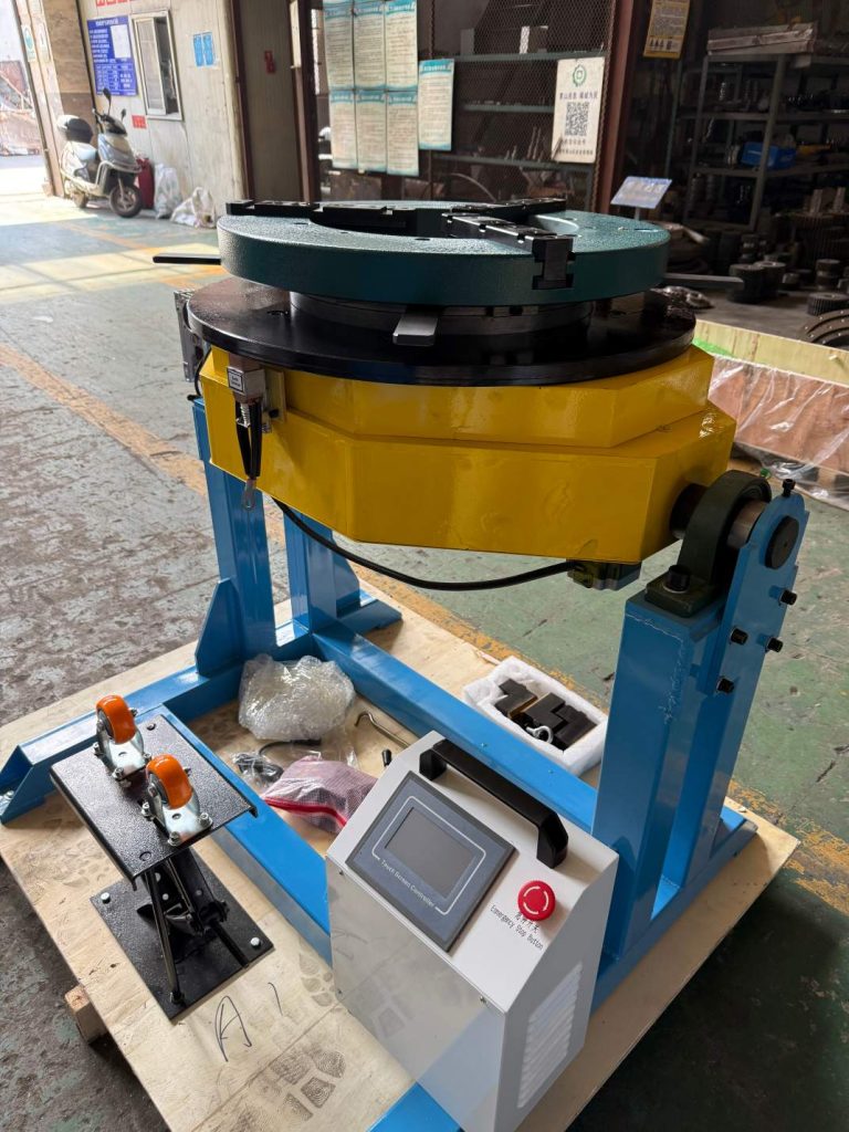
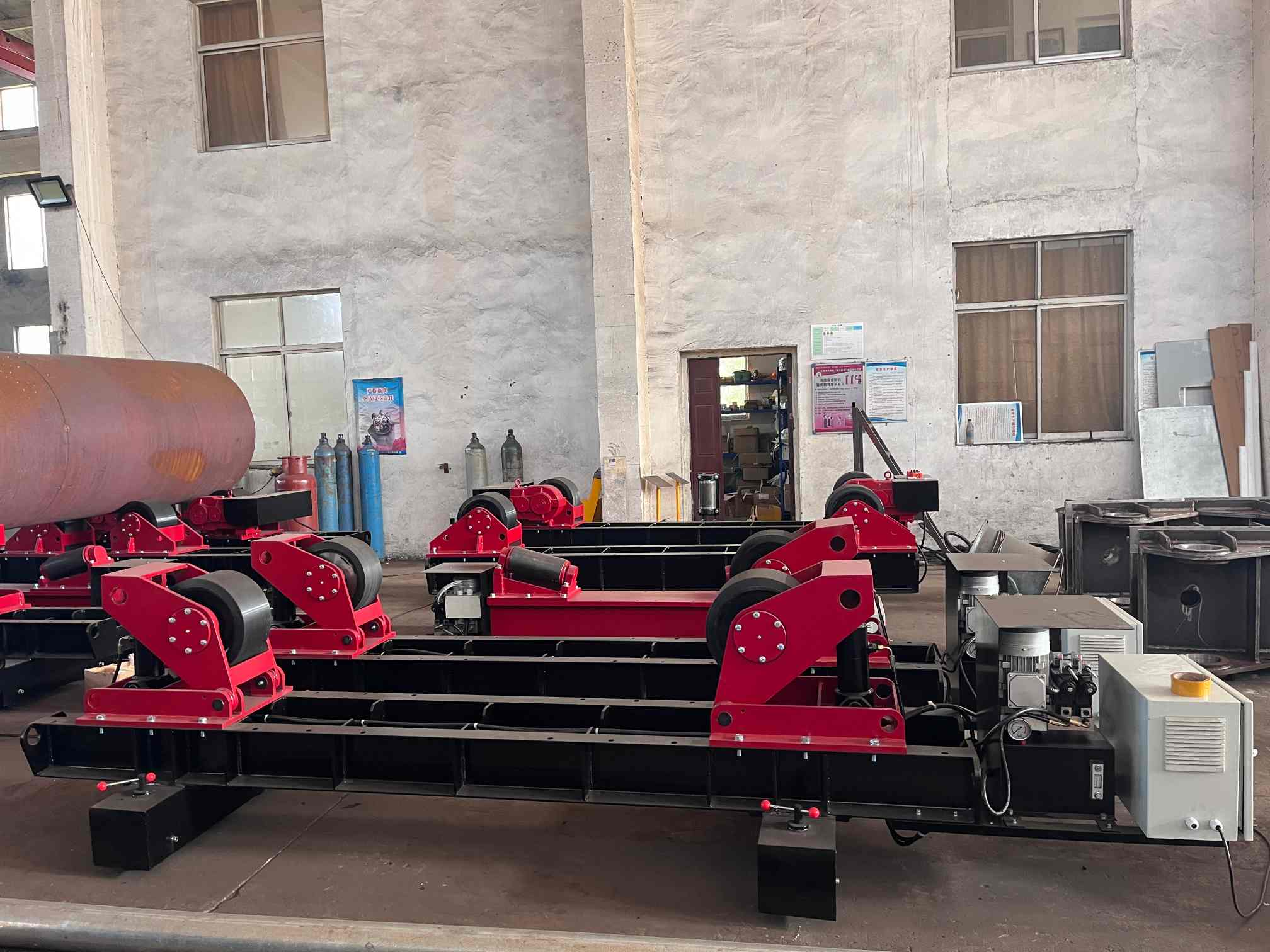
On rotating work, the same .035 parameters apply. A positioner that keeps the joint turning at steady speed removes a variable from travel speed while you concentrate on stick-out.
Having Trouble With .035 Hardwire Settings on Your Production Line?
Most .035 hardwire problems are not solved by another generic voltage chart; they come from the interaction between the power source, the wire drive, and the joint prep. If the weld team has already added voltage and the puddle still looks cold or too wet, the issue usually sits in stick-out tolerance, gas coverage, or a machine mismatch that a chart cannot see.
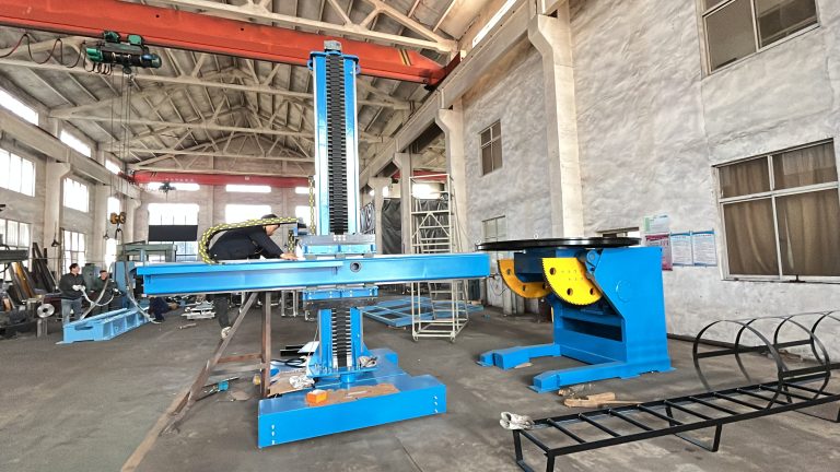
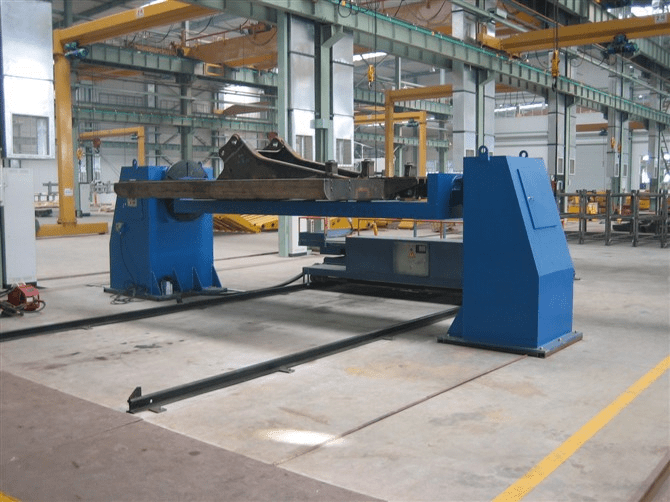
As a welding automation manufacturer, Wuxi ABOKE Machinery builds cells for manipulator and positioner work where solid MIG wire is part of the process. We can confirm the parameter window and the correct wire drive interface for your joint.
Send your material thickness, wire specification, and a short video of the weld to [email protected] or call +86 13616174307. We will go through your .035 hardwire settings against your equipment and give you the next correction.
What Do Welders Ask About .035 Hardwire Settings?
Does .035 Hardwire Need a Special Drive Roll?
Use a smooth U groove roll for .035 solid wire. A knurled V roll only makes sense if the feeder cannot maintain steady tension, and even then I test it before using it in production. Too much tension flattens the wire and drags through the liner, which looks like an arc setting problem but is mechanical. I specify smooth U groove rolls on most production cells to keep the copper coating intact.
Can I Run .035 Hardwire on a 115 Volt MIG Machine?
Many welders assume a 115 volt machine cannot run .035, but the real limit is wire feed speed under load. The machine may push 130 to 180 ipm with .035 on 18 gauge, yet it usually lacks the headroom to reach the 300 ipm and 20 volt range needed for 1/8 inch plate. If most work is 1/8 inch or thicker, step down to .030 wire or move to a 230 volt machine.
Why Does My .035 Hardwire Weld Leave Brown Glass Islands and Soot?
It depends on whether the islands sit on the toes or float on the weld surface. Toe islands usually mean insufficient shielding gas or too much stick-out. Islands floating in the puddle usually mean the voltage is too high and the arc is disturbing the molten pool before the silica can float out. Lower the voltage half a volt and tighten the nozzle distance before you adjust gas flow.
Is .035 Hardwire Worth Changing From .030 for 1/8 Inch Plate?
In production runs I have moved from .030 to .035 on 1/8 inch plate when the weld count was high enough to justify the larger puddle and slightly faster fill. The .035 wire carries more current but is less forgiving on thin edge joints and gaps. If your parts are tight and repetitive, .035 pays off. If fit-up varies, .030 stays easier to control. Share your current wire diameter and production rate with [email protected] and I will confirm whether the change is worth it for your work.
If you’re interested, check out these related articles:
Precision Positioning for Pipe and Shaft Welding Workpieces
Automating Wind Tower Welding: Boost Productivity and Quality
Boiler Production Lines: Tube to Panel Manufacturing Explained
Heavy-Duty Welding Rotators with 200 Ton Load Capacity
H-Beam Assembly: Automated Web and Flange Fit-Up Precision