
US Wind Turbine Manufacturers: 2024 to 2026 Buyer’s Guide
Table of Contents
- Who Are the Leading US Wind Turbine Manufacturers in 2024 to 2026?
- Why Does the US Wind Turbine Supply Chain Depend on Welded Towers?
- What Welding Equipment Do Wind Tower Shops Need for Serial Production?
- How Should a Fabricator Plan a Wind Tower Welding Line?
- When Should a Shop Lock In Welding Equipment for US Turbine Work?
- What Should Buyers Ask About Wind Tower Welding Equipment?
- Do I need submerged arc welding for tower longitudinal seams?
- What rotator capacity should I specify for tower shells?
- How do I compare Chinese welding line suppliers for a US wind turbine program?
- When does a positioner make more sense than a rotator?
Tracking US wind turbine manufacturers in 2024 through 2026 means looking beyond turbine nacelle assembly. The names that matter are the OEMs and fabricators with production capacity in the United States, but the larger constraint is often the welded tower, flange, and foundation work behind them. A buyer’s list of turbine OEMs does not solve schedule risk if the supplying shop cannot hold root gap, shell roundness, and weld sequence. I see this same gap when wind tower shops call us about line layout after their order book has already filled.
Who Are the Leading US Wind Turbine Manufacturers in 2024 to 2026?
The short list for onshore wind in the United States still runs through GE Vernova, Vestas, Siemens Gamesa, and Nordex. GE Vernova carries the broadest domestic OEM footprint, with nacelle and blade operations tied closely to US projects. Vestas runs multiple Colorado plants and holds the deepest plant-level presence among non-US turbine makers. Siemens Gamesa keeps blade and nacelle capacity in Iowa and Kansas, though its order flow moves in cycles. Nordex operates a smaller Iowa nacelle plant and stays selective about projects.
| Company | Main US Production Focus | What It Means for Fabrication Shops |
| GE Vernova | Nacelle assembly, blade production, and US onshore project supply | Strong pull for domestic tower and heavy weld capacity |
| Vestas | Blade and nacelle production across Colorado | Regional tower sourcing with serial production rhythms |
| Siemens Gamesa | Blade and nacelle capacity in Iowa and Kansas | Smaller but detailed US order flow with strict documentation |
| Nordex | Nacelle assembly in Iowa | Selective orders that favor flexible fabrication shops |
| Broadwind | Heavy weld fabrication for towers and industrial systems | Direct partner capacity for turbine structures |
| Arcosa Wind Towers | Tower manufacturing | Active demand signal for shell welding and fit-up equipment |
The list itself does not tell a fabricator where orders will land. A shop that already supplies towers to one of these programs tends to see repeat demand when its weld documentation and roundness records are clean.
Why Does the US Wind Turbine Supply Chain Depend on Welded Towers?
A wind turbine tower is a stack of rolled steel shells, each with longitudinal seams and circumferential joints. The value sits in dimensional control as much as weld metal. When a shell arrives at the girth welding station out of round, the crew spends time pulling it back with dogs, strongbacks, or jacks before the root pass can begin. That correction time multiplies across a multi-section tower.
In the tower programs I have worked on, the busiest station is almost always the longitudinal seam weld. If the column and boom travel speed does not match the submerged arc welding parameters, the shop either slows the arc or spends extra hours grinding and rewinding. The first failure is not a bad weld. It is lost station time.
What Welding Equipment Do Wind Tower Shops Need for Serial Production?
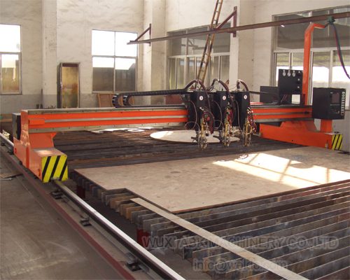
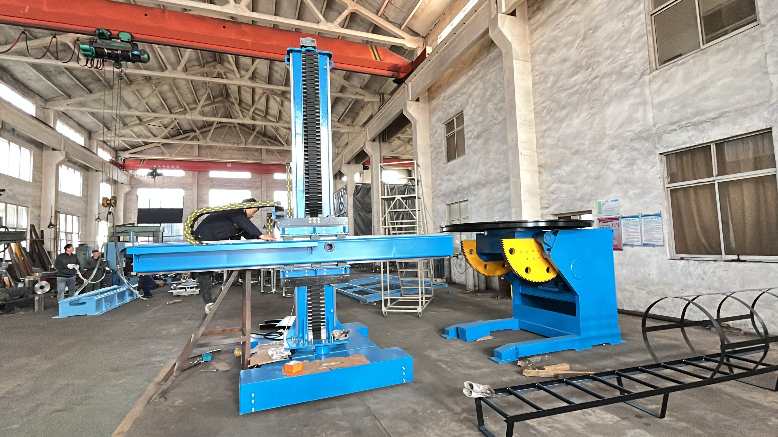
Most shops do not start with a single machine. They start with the flow from plate cutting to shell fit-up, longitudinal seam welding, girth seam welding, and surface treatment. The core machines are welding rotators for shell rotation, column and boom manipulators for submerged arc welding, fit-up rotators for shell alignment, and CNC cutting for beveled plate edges. A shot blasting step after welding prepares the surface for paint and inspection.
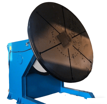
More important than the machine list is the load path. A rotator that is rated for a static shell but not for off center roll inertia will creep, slip, or overload at start and stop. In wind tower work, that shows up as irregular weld bead spacing on long circumferential seams.
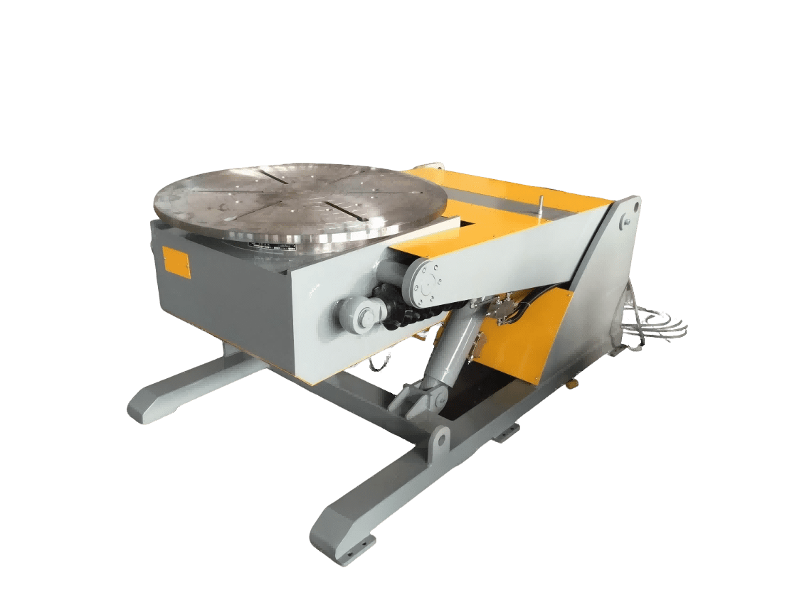
If your program involves shell diameters above 4 meters or longitudinal seams longer than 10 meters, confirm rotator load distribution and boom stroke before finalizing a BOM. Send the shell diameter, wall thickness, and monthly section target to [email protected], and we can cross-check the machine configuration against your weld procedure.
How Should a Fabricator Plan a Wind Tower Welding Line?
A line that works for a 3 meter tower may not work for a 4.5 meter tower. The easiest planning sequence is:
- Map plate cutting, edge beveling, and shell rolling as one material stream.
- Size the rotators for the heaviest shell plus the weight of the welding head and cables.
- Match the column and boom reach to the deepest internal longitudinal seam.
- Reserve fit-up space near the girth station for ovality correction before root pass.
- Add shot blasting capacity after welding so coating does not queue behind fabrication.
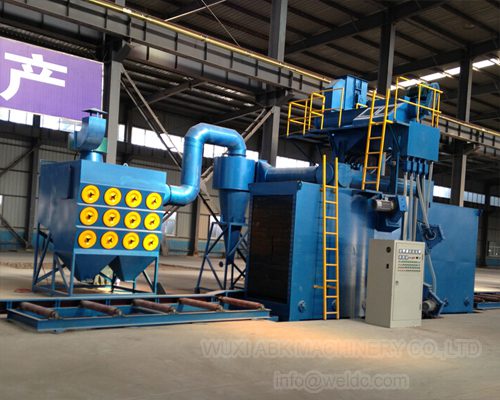
Some shops skip the fifth step and then find painted sections waiting while the blast booth becomes the bottleneck. The line can only run as fast as the slowest station, and in practice that station changes with shell diameter and order mix.
When Should a Shop Lock In Welding Equipment for US Turbine Work?
The riskiest time to plan a wind tower welding line is after the frame agreement is signed. Fabrication shops that wait for the order often lose four to six months to engineering, cable routing, foundation work, and commissioning. That window collides with the OEM’s installation schedule.
A more workable approach is to define the shell range, monthly section output, and weld procedures before the tender stage. Then the equipment list writes itself. You know the rotator capacity, the boom stroke, and the number of stations.
If you sell into US wind turbine manufacturers or are preparing to, send your tower diameter, shell thickness, and monthly output target to [email protected] or call +86 13616174307. We can propose a layout matched to the floor, crane path, and submerged arc welding sequence, not a catalog list.
What Should Buyers Ask About Wind Tower Welding Equipment?
Do I need submerged arc welding for tower longitudinal seams?
For most onshore tower shells above 20 mm wall thickness, submerged arc welding is the fastest way to fill a long seam with consistent penetration. Heavy wire MIG or flux core can work for fit-up and repair, but they do not keep the same deposition rate across a 12 meter joint. The deciding factor is not the machine itself but whether the column and boom travel speed can hold steady while flux delivery and wire feed run at the procedure setting. If speed drifts, the bead width changes and the inspection record becomes harder to defend.
What rotator capacity should I specify for tower shells?
It depends on the maximum shell weight and how far the center of gravity shifts during rotation. A shell with a door frame or internal brackets rotates eccentrically, so the driven and idler rollers need enough load margin to hold start and stop without slip. Specify the heaviest shell plus the welding head load, then add at least 15 percent for uneven distribution. The rotator builder must confirm roller spacing against the smallest and largest diameter in the same unit, because a wide setting for a large shell may not grip a narrow section.
How do I compare Chinese welding line suppliers for a US wind turbine program?
Many buyers assume the lowest quote is the most useful comparison. It rarely is. For US wind tower work, compare the supplier’s drawings against your foundation loads, crane hook height, and electrical voltage before price. Ask for the weight and footprint of each station, the welding procedure documentation, and the spare parts list for main drives and rollers. If a supplier cannot show the gearbox and motor calculation for your heaviest off center condition, the quote is incomplete. The equipment must fit the actual shell range, not the sample case shown in a brochure.
When does a positioner make more sense than a rotator?
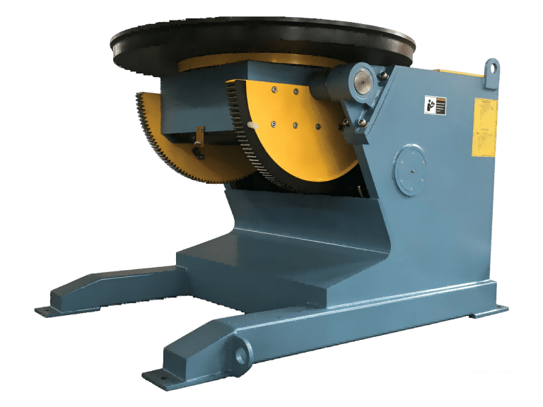
A positioner is better for flanges, door frames, and smaller cylindrical parts that need rotating and tilting in a fixed station. A rotator is better for long tower shells that rest on roller beds and rotate around their own axis. Confusing the two is a common planning mistake. If the part is short enough for the table or chuck to hold safely, a positioner gives better access for fillet welds around a flange. If the part is a full shell section, use rotators and a column and boom. If you are already quoting work to US wind turbine manufacturers and need a station layout, share your part size and weight range with [email protected] and we will identify which machine type fits before you commit.
If you’re interested, check out these related articles:
Custom Welding Automation Solutions for Industrial Manufacturing
H-Beam Assembly: Automated Web and Flange Fit-Up Precision