
Fabrication Welding: Process Planning and Quality Control
Table of Contents
- Fabrication Welding Process Planning
- Material Preparation and Fit-Up
- Common Fabrication Welding Processes
- Quality Control and Automation in Fabrication Welding
- Planning Support for Fabrication Welding
- Common Questions About Fabrication Welding
- What is the difference between fabrication welding and general welding?
- Which welding process is best for heavy steel fabrication?
- How do I reduce distortion during fabrication welding?
- When should I automate fabrication welding?
Fabrication welding is not one skill; it is a sequence of decisions that determines whether a fabricated structure passes inspection on the first attempt or enters a rework cycle. Most articles on this topic describe welding processes in isolation. This article focuses on the planning, fit-up, quality, and equipment decisions that separate predictable shops from disrupted ones. We have seen projects succeed or stall based on tolerances set days before welding begins. For engineers and buyers, the practical path is to lock process requirements before cutting, then match automation only where weld volume justifies it.
Fabrication Welding Process Planning
Fabrication welding sits at the end of cutting, forming, and fit-up, which means it inherits every tolerance from earlier operations. The planning step should fix joint type, process, and sequence before material reaches the weld cell.
Start with the joint. A groove weld on thick plate requires a defined bevel angle, root face, and root opening. A fillet weld on structural steel is more forgiving but still needs a controlled root gap. When these values are missing from drawings, the welder is forced to make decisions that were never approved, and those decisions rarely improve quality.
Process selection should be driven by material thickness, position, and production volume. A shop welding long seams in 10 mm plate can consider submerged arc welding, but only if it has the manipulator or rotator to keep travel speed consistent. A fabrication cell with many short, positional welds may do better with FCAW or GMAW because the equipment is lighter and easier to move around the workpiece.
Sequence planning is where shops create or lose stability. Welding near the neutral axis first, alternating sides, and using back-step runs can reduce angular distortion before it becomes a problem. In a pipeline fabrication project I supported, we stopped accepting plate blanks from the saw until bevel angles were checked against a jig at the cutting station. Fit-up delays dropped because fitters no longer corrected bevel geometry by grinding at the weld cell.
The planning phase should also produce a realistic inspection hold point list. If a pressure vessel or boiler component requires nondestructive testing, the weld procedure must be fixed before production starts. Changing the process after welding has begun is the fastest way to create a documentation mismatch.
Material Preparation and Fit-Up
Material preparation determines whether a good fabrication welding procedure can be executed. Plate and pipe should arrive clean, with mill scale removed where the code requires it, and with edge geometry matching the approved joint design. Moisture and oil on the joint can cause porosity, so cleaning is not a cosmetic step.
Fit-up is where many fabrication sequences fail. A root gap that is too wide increases weld metal volume and shrinkage. A land that is too thick can prevent full penetration. Misalignment between two sections forces the welder to compensate with angle or speed, and that compensation shows up later as undercut or lack of fusion. Shops that control fit-up before tacking spend less time repairing completed welds.
Tack welds are part of fit-up, not an afterthought. They should be made by qualified welders using the same filler classification as the production weld where possible. Short, correctly spaced tacks hold alignment without locking in excessive stress. If tacks are too long or too heavy, they create their own defects that the final pass may not fully remelt.
If your fabrication sequence includes stainless steel vessels with wall thickness above 10 mm, it is worth confirming the bevel angle and root face tolerance with your equipment supplier before finalizing the BOM. Send your joint details to [email protected] and we will confirm the fit-up parameters.
Common Fabrication Welding Processes
The process selected for fabrication welding changes the entire production logic. The table below compares the processes most often used in industrial fabrication.
| Process | Best Use | Key Limitation |
| SMAW | Field repairs and short structural welds | Lower deposition rate, slag removal between passes |
| GMAW | Thin and medium plate with clean fit-up | Sensitive to surface contamination and wind |
| FCAW | Structural steel and open-shop fabrication | Higher fume levels, slag removal required |
| GTAW | Stainless pipe roots and precision joints | Slow, requires high operator control |
| SAW | Long straight and circumferential seams | Restricted to flat or horizontal positions |
SMAW remains common because it tolerates less-than-perfect fit-up and works outdoors, but its deposition rate limits output on large fabrication runs. GMAW is fast and adaptable, yet it needs clean joints. FCAW offers more tolerance for light shop conditions while still delivering high deposition rates, which is why many structural fabricators run it as their baseline process.
GTAW is the default for root passes in stainless and alloy piping because puddle control beats speed. It is slower, so it usually appears only where code or material demands it. SAW is the productivity choice for plate and vessel seams when a manipulator or turning roll can hold the torch over the joint. The arc is hidden under flux, so process control depends on joint preparation and equipment alignment.
Which process is best is the wrong starting point. A fabricator should ask whether the shop can feed the process with consistent fit-up and position the workpiece. If not, the most productive process on paper will produce rework on the floor.
Quality Control and Automation in Fabrication Welding
Quality control in fabrication welding begins before welding starts. Pre-weld checks should verify base material grade, joint dimensions, cleaning, and tack quality. During welding, the variables that create most defects are voltage, travel speed, and heat input. In manual work, these variables drift with operator fatigue and position changes. In mechanized work, they are set once and repeated.
The most common defects I see from fabrication shops are not exotic metallurgical failures. They are porosity from dirty joints, undercut from excessive travel speed, and lack of fusion from poor fit-up or low heat input. Each has a specific mechanism. Porosity forms when gas is trapped in the solidifying weld pool. Undercut removes base metal along the toe. Lack of fusion occurs when the weld metal does not melt the base metal or previous pass completely.
Assigning priority matters. Fit-up tolerance is the highest-leverage control because it affects access, deposition, and inspection results downstream. If a shop controls root opening and alignment before welding, later process adjustments become smaller. If fit-up is loose, even a well-qualified procedure will underperform.
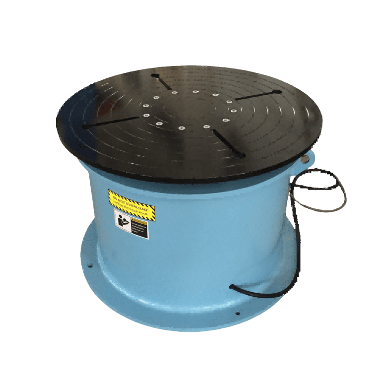
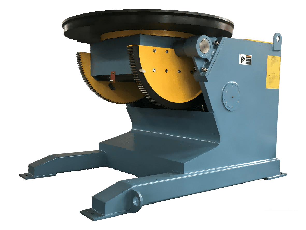
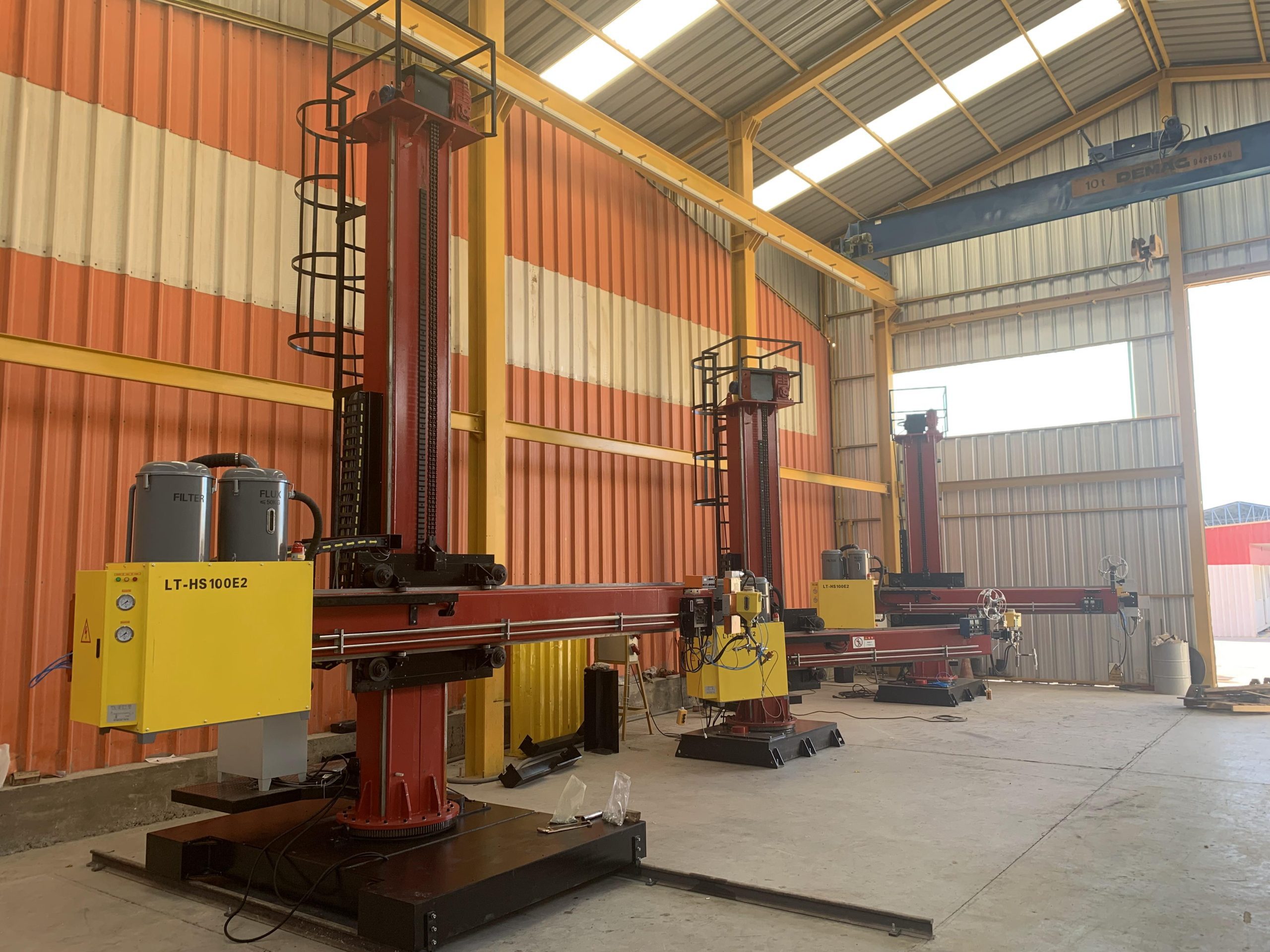
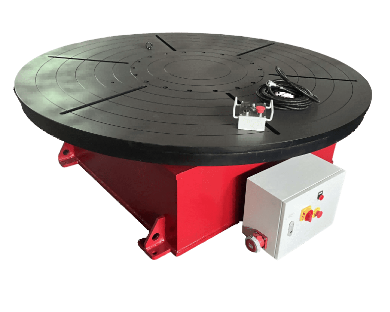
Automation becomes the right conversation when weld volume or repeat geometry makes manual variation expensive. A welding manipulator with a column and boom handles long straight seams without operator fatigue. Self-aligning or conventional rotators rotate vessels so circumferential seams stay in the flat position. A three-axis hydraulic positioner tilts complex parts to keep the weld puddle horizontal. These tools do not replace judgment; they remove repeatable motion variables from the process.
Our equipment at Wuxi ABOKE Machinery is built to ISO and CE requirements, with welding manipulators, rotators, and positioners configured for pipeline welding, structural fabrication, and vessel work. When buyers send drawing details early, we can recommend the right load capacity and travel range before the foundations are poured.
Planning Support for Fabrication Welding
Fabrication welding projects lose more time to unclear joint specifications and mismatched equipment than to the welding itself. A drawing that says only full penetration without a bevel detail leaves the supplier guessing. A rotator sized without accounting for off-center load can stall before the first production weld.
The practical step is to send the part drawings, material grades, and monthly weld volume before finalizing the equipment list. We review the workpiece center of gravity, diameter range, and seam position, then confirm which manipulator, rotator, or positioner matches the shop layout and power supply. This step closes the gap between a generic quotation and a production cell that actually runs.
Send your part drawings and planned weld meters per month to [email protected] or call +86 13616174307. We will confirm load capacity, control options, and CE documentation before you issue a purchase order.
Common Questions About Fabrication Welding
What is the difference between fabrication welding and general welding?
Fabrication welding is welding performed as part of a fabricated metal product sequence, not a separate process. The difference is control. Fabrication welding must account for cutting tolerances, forming springback, fit-up gaps, and inspection requirements before the first arc is struck. General welding can sometimes be isolated to a single joint. Fabrication welding cannot. The person planning the weld should think backward from final inspection to raw material, because each earlier operation sets the conditions the welder must handle.
Which welding process is best for heavy steel fabrication?
It depends on joint configuration and monthly volume. For thick plate long seams, submerged arc welding is usually the right first choice because it offers deep penetration and high deposition rates when paired with a column and boom manipulator. For open-shop structural work, FCAW balances deposition and tolerance to shop conditions. For stainless pipe roots, GTAW remains the standard because puddle control matters more than speed. A shop with a mixed workload should choose equipment that handles several processes rather than locking itself into one.
How do I reduce distortion during fabrication welding?
A common assumption is that weld sequence matters only after fit-up is correct. The opposite is true. Distortion is driven by heat input, and heat input is controlled by weld size, travel speed, and sequence. We reduce distortion by balancing welds around the neutral axis, using back-step or intermittent sequences, and completing short welds first so they act as fixturing before long seams are welded. If long continuous seams are welded on one side first, no amount of post-weld straightening will fully restore the shape.
When should I automate fabrication welding?
In shops I have supported, automation is worth evaluating when monthly weld volume is high enough that a positioner or manipulator runs for several hours per shift, not only for one project. A simple starting point is arc-on time. If a rotator or manipulator can lift arc-on time from roughly 20 percent to 40 percent, payback is usually quick. For job shops with small batches, a manual adjustable height positioner may cover most of the benefit. Share your monthly weld meters and joint details with [email protected], and we will confirm whether automation makes sense for your workload.
If you’re interested, check out these related articles:
Heavy-Duty Welding Rotators with 200 Ton Load Capacity
L-Type Welding Positioners: Applications and Load Capacity Guide
Welding Manipulators for Storage Tanks: Girth and Seam Automation
Evaluate ROI of Welding Automation Business Investment