Welding Process Pros and Cons: Do Benefits Outweigh Drawbacks?
Table of Contents
- What Welding Processes Deliver That Other Joining Methods Cannot
- The Cons That Show Up After the Invoice
- Where Each Welding Process Earns Its Keep
- Fit-Up and Edge Preparation Decide More Than the Process
- Positioning and Mechanization Shift the Cost Equation
- When Welding Is the Wrong Answer
- The Checks That Confirm the Pros Will Hold on Your Job
- Getting the Setup Right Starts With the Job Details
- FAQ
- Do the pros of welding processes really outweigh the cons?
- Which welding process offers the best balance for general fabrication?
- How much does fume control add to a welding project?
- Can distortion be prevented rather than corrected?
- References
Everyone agrees that the pros of welding processes outweigh the cons, and for most heavy fabrication that consensus holds. Fusion welding produces a continuous, pressure-tight joint without drilling fastener holes, and it keeps that advantage at plate thicknesses where bolting stops being practical. The margin is narrower than the slogan implies. Distortion, fume exposure, and rework scale with fit-up, positioning, and procedure control rather than with the process name alone, and in a few applications the balance tips the other way. Separating the pros that come from the process itself from the pros that come from how the work is set up is what makes the comparison worth reading.
What Welding Processes Deliver That Other Joining Methods Cannot
The core advantage is metallurgical continuity. Inside the fusion zone and the heat-affected zone, the joint behaves as one piece of metal rather than two surfaces held together by bearing pressure. Most of the other advantages follow from that one property. A bolted connection needs holes, and every hole removes section, concentrates stress, and creates a path for leakage. A welded connection needs none of them, which is why pressure vessels, process pipe, and cyclically loaded structures are welded rather than clamped.
Thickness range follows the same logic. One process family covers thin sheet and plate beyond 100 mm by changing current, filler metal, and pass sequence. Scaling a bolted joint from thin plate to heavy section means larger plates, larger drills, torque control, and a joint that still depends on friction staying stable for decades. Scaling a welded joint means more passes and a procedure that was qualified for that range.
Field repairability is the third advantage buyers rarely count until they need it. Weld metal can be removed by arc gouging or grinding and re-deposited on site with portable equipment. A worn wear plate or a cracked bracket can be restored without dismantling the assembly around it.
What turns these benefits from claims into records is the qualification system built around them. AWS D1.1 [1] converts a structural welding claim into procedure qualification, welder performance qualification, and acceptance criteria. ISO 3834-2 [2] does the same at fabricator level by defining what a comprehensive quality management system for fusion welding must contain. Without that framework, “the weld is strong” is an opinion. With it, the claim can be inspected, documented, and defended.
| Benefit | How the process produces it | What it does not prove |
|---|---|---|
| Continuous joint | Fusion and controlled solidification bond weld metal to base metal across the joint face | That the joint matches base metal toughness in every direction; the heat-affected zone is a separate metallurgical condition |
| No fastener holes | Load passes through the weld rather than through bearing on a drilled hole | That the joint is stronger than the plate; an undermatching filler can be the weaker link by design |
| Thickness range | Current, filler, and pass sequence are adjusted to the section being joined | That one procedure covers every thickness; each qualified range has limits |
| Field repairability | Weld metal can be cut out and re-deposited with portable equipment | That a field repair restores original design life without re-inspection |
| Pressure tightness | Full penetration welds form a continuous barrier across the joint | That a passing leak test proves fusion; a tight joint can still contain lack of fusion |
The Cons That Show Up After the Invoice
The first con is distortion, and it is mechanical rather than mysterious. Welding heats a narrow band of metal while the surrounding plate stays cool. The hot band tries to expand and is restrained, so it yields in compression; on cooling it contracts and drags the restrained material with it. The visible results are angular distortion under fillet welds, bowing along long seams, and shrinkage that shortens the assembly. Correction means straightening, machining, or extra allowance, and each of those adds cost after the weld is already complete.
The second con is exposure. The International Agency for Research on Cancer classified welding fumes as Group 1, carcinogenic to humans [3], which places welding in the same hazard category as asbestos and crystalline silica. Ultraviolet radiation from the arc causes arc eye and skin burns, and gas metal arc welding on aluminium generates ozone. Control is not optional: OSHA 29 CFR 1910.252 sets ventilation and protection requirements for welding, cutting, and brazing [4], and ANSI Z49.1 provides the detailed safe practice for the same operations [5]. In production terms that means extraction at the arc, general ventilation, respiratory protection where extraction cannot hold exposure down, and screens to protect nearby workers.
The third con is skill dependence. Manual weld quality tracks operator consistency, because travel speed, work angle, arc length, and interpass cleaning all drift with attention and fatigue. Two welders working to the same procedure can produce different bead profiles and different defect rates. Welder qualification sets a floor for competence, but a floor is not a ceiling.
Manual welding ties output to operator pace, and the gap against a positioned setup appears mainly in travel speed consistency and rework rate. <Pipe Welding Rotator vs Manual Welding | Productivity and Cost Comparison> covers how the two approaches compare on productivity and cost.
The fourth con is qualification and inspection overhead. A procedure must be qualified before production, welders must be tested, and the finished joint must be examined. Visual, penetrant, magnetic particle, ultrasonic, and radiographic methods each cost time and money, and each finds a different family of defects. On a small batch of low-value parts, that overhead can exceed the value of the joint itself.
A fifth con appears only in certain steels. Hydrogen-assisted cold cracking needs three conditions at once: diffusible hydrogen, a susceptible microstructure, and tensile stress. Remove any one and the mechanism stops. The practical response is low-hydrogen consumables, controlled preheat, and a heat input range that keeps the microstructure out of its hardest condition. It is manageable, but it is not free.
Where Each Welding Process Earns Its Keep
The ratio of pros to cons is not a property of welding in general. It is a property of a specific process applied to a specific joint. The five arc processes that dominate industrial fabrication differ mainly in deposition rate, position tolerance, and how much of the result depends on the operator.
Deposition rate drives cost on thick sections, because labour is charged by the hour while weld volume is fixed by joint geometry. Position tolerance drives feasibility, because a process that only runs flat cannot make a field joint on an erected structure. Operator contribution drives variance, which drives inspection and rework.
| Process | Strongest case | Where the balance tips against it | Note on qualification |
|---|---|---|---|
| SMAW | Site work, repair, windy conditions, all positions, simple equipment | High-volume production and heavy multi-pass work where deposition rate governs cost | Narrow current and electrode ranges; slag must be removed between passes |
| GMAW | High deposition in flat and horizontal position, automation friendly, clean finish | Outdoor work in wind, and sites without a reliable shielding gas supply | Draft displaces shielding gas, and porosity follows quickly |
| FCAW | Deposition above stick with better wind tolerance, structural fabrication | Confined spaces with limited fume extraction; work needing very low hydrogen without controlled consumable storage | Flux-cored wire needs storage control to keep hydrogen low |
| GTAW | Root passes, thin material, stainless and aluminium, precise control | Thick structural sections on a production schedule | Deposition is low, so cost per metre is high |
| SAW | Long straight seams on thick plate, tanks, beams, wind tower shells | Out-of-position joints and short irregular seams | Granular flux needs handling, recovery, and drying |
Procedure qualification ties the comparison together. ASME BPVC Section IX [6] defines how a welding procedure and a welder are qualified for pressure equipment, and the essential variables it lists, including process, filler classification, thickness range, position, preheat, and heat input, are the same variables that decide whether the advantages on the left of that table survive on a real job. A process is not selected in the abstract. A qualified procedure is selected for a defined range of thickness and position.
Fit-Up and Edge Preparation Decide More Than the Process
Before the arc starts, two decisions already fix how much distortion and how many defects the job will produce: joint geometry and edge quality.
Root gap and bevel angle set the volume of weld metal required. A gap that varies around a circumference produces a weld that varies in volume, and a weld that varies in volume shrinks differently at different points. That is how a joint that measured within tolerance at fit-up ends up outside tolerance after welding. A consistent root gap is worth more to distortion control than a change of process.
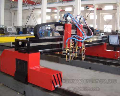
Edge quality comes from the cutting method. Flame cutting leaves an oxide layer and a heat-affected zone along the cut face, and high-integrity joints usually require that material to be ground back before welding.
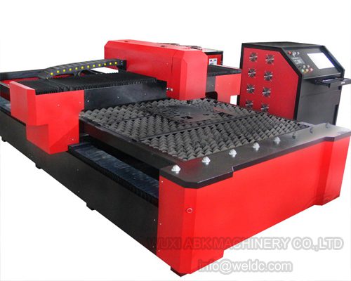
Laser cutting produces a narrow kerf, a small heat-affected zone, and a square edge that often needs little further preparation before fit-up.
Plasma cutting sits between the two, with dross on the underside that has to be removed before the joint is closed.
Alignment is the third variable. Two shell sections that are each round can still present a varying gap when their centrelines do not coincide, because ovality and mismatch both appear as gap variation. Both are corrected before tacking or not at all.
Ovality and misalignment force the root gap to change around the circumference, which changes weld volume and shrinkage pass by pass. <Fit-Up Rotator for Accurate Vessel Alignment & Stable Welding> covers how a fit-up rotator keeps vessel alignment stable before welding begins.
Positioning and Mechanization Shift the Cost Equation
The largest controllable factor in weld cost is position. Welding flat allows higher current, larger beads, better fusion, and easier viewing than vertical or overhead work at the same procedure. Everything a fabricator does to turn the joint toward flat is a productivity decision before it becomes a quality decision.
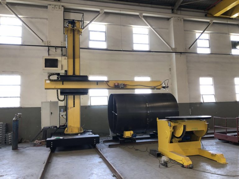
Rotators handle cylindrical work. Powered rolls support a vessel or pipe section and turn it at a set surface speed, so the arc stays in the flat or horizontal position while the workpiece moves beneath it. Travel speed becomes a machine setting rather than an operator judgement, which is why circumferential seams welded on rolls look different from seams welded with the workpiece static.
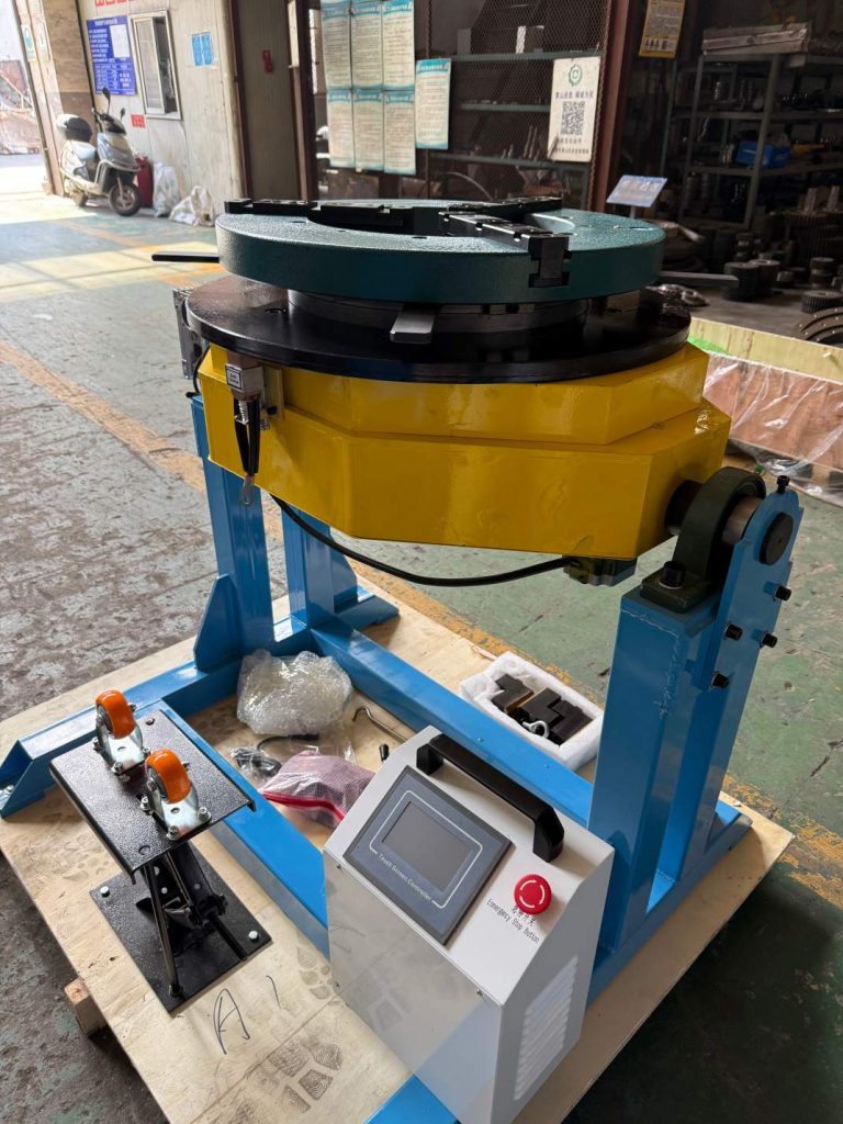
Positioners do the same for irregular geometry. A turntable rotates work about a vertical axis, a tilting table presents an angled face, and a head and tail unit holds a long workpiece between centres and rotates it about a horizontal axis.
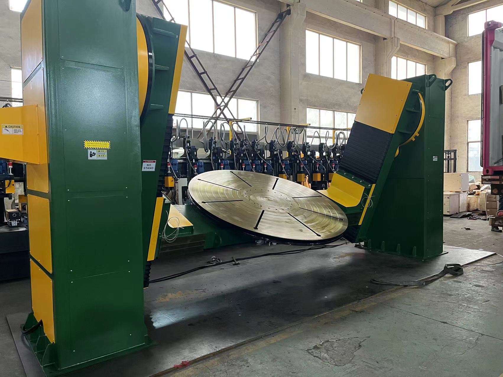
For a batch that mixes several diameters, an adjustable unit is the more flexible choice, because height and tilt can be reset without rebuilding the station.
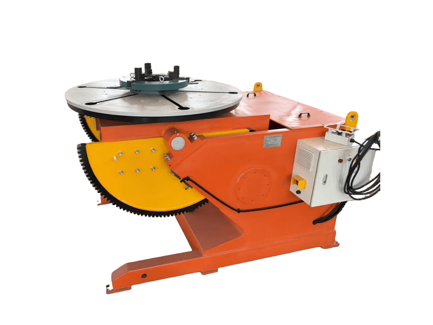
The choice between a fixed and an adjustable positioner usually comes down to how many workpiece diameters the station handles and how often the working height changes. <Fixed vs Adjustable Welding Positioners: How to Choose the Right Tool> covers the selection criteria for that decision.
Manipulators move the torch instead of the work. A column and boom carries the welding head along a seam, holds a fixed distance from the surface, and takes the operator off a ladder or scaffold. On long straight seams in shells and beams, that arrangement is what makes submerged arc welding practical at all.
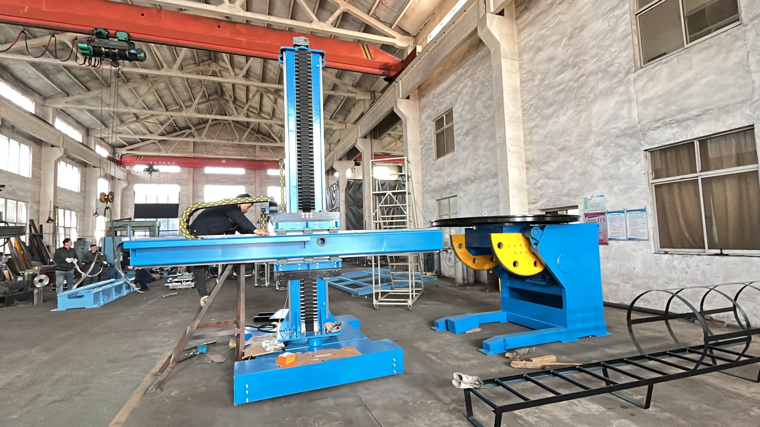
None of this changes the metallurgy. Positioning changes the share of the job that depends on operator steadiness, and that share is the part of the con column most buyers can actually remove.
When Welding Is the Wrong Answer
An honest comparison has to name the cases where the answer is no.
Very thin sheet is the clearest. At sheet thicknesses where heat input cannot be held down without burn-through, a structural adhesive or a mechanical fastener can produce a flatter, faster result. Laser welding narrows that gap considerably, so the exclusion applies to arc processes rather than to welding as a category.
Dissimilar metal pairs that form brittle intermetallics are the second case, with aluminium to steel as the familiar example. The joint can be made, but the interface produces a hard, brittle layer whose thickness decides whether it survives fatigue. Brazing, mechanical fastening with isolation, or a transition insert avoids the problem instead of managing it.
Third, assemblies that must come apart. A welded joint is permanent by design. Where maintenance access, transport, or modular replacement requires separation, a bolted connection is the correct answer, and no amount of weld quality compensates for the wrong choice.
Fourth, low-value parts. When a component is small, lightly loaded, and made in low volume, the cost of procedure qualification, welder qualification, and inspection can exceed the value of the part.
Fifth, confined spaces where fume cannot be extracted. If exposure cannot be controlled where the work must be done, that health constraint carries the same weight as any technical one.
The Checks That Confirm the Pros Will Hold on Your Job
These checks confirm, before production starts, that the advantages argued for will actually appear on the specific job.
Confirm the governing code. Structural steel, pressure equipment, and marine work each carry different acceptance criteria, and AWS D1.1, ASME BPVC Section IX, and EN 1090-2 do not accept the same things. The code decides the inspection method, the acceptance level, and the documentation, so write the code and edition into the purchase specification.
Match base metal and thickness to a qualified procedure. A procedure qualified on thin plate does not automatically cover heavy section. Check the qualified thickness range and the essential variables before quoting.
Confirm welder qualification. ISO 9606-1 [7] defines how a welder’s competence is tested and what the certificate covers. The certificate must match the process, position, and thickness in the actual job.
Fix joint preparation and tolerance in writing. Bevel angle, root face, root gap, and edge quality belong on the drawing rather than in a verbal instruction. Record the cutting method, because it decides whether edge grinding is included in the price.
Decide position and access before choosing equipment. If the joint can be rotated to flat, welding cost falls and quality risk falls with it. If it cannot, that constraint belongs in the plan from the first review.
Agree the inspection method and acceptance criteria before the first weld. Different testing methods find different defects, and choosing the method late usually means choosing it under schedule pressure.
Plan fume control together with the layout. Extraction at the arc, general ventilation, and respiratory protection are far easier to install before the workstation is built than to retrofit around positioners and rotators afterwards.
Getting the Setup Right Starts With the Job Details
Most of the balance between pros and cons is decided before the first arc: joint design, position, and the equipment holding the workpiece. Send the base metal and grade, thickness range, joint type and welding position, workpiece diameter, length and weight, the governing code, the required inspection method, production volume, and whether the work happens in a shop or on site. With those details, WUXI ABK MACHINERY CO., LTD can review which positioning or handling configuration fits the job, and where a standard unit is enough. Contact [email protected] or +86 13616174307 to start that review.
FAQ
Do the pros of welding processes really outweigh the cons?
For structural, pressure, and heavy fabrication work, yes, provided the job is set up to control the two cons that scale worst: distortion and fume. Welding delivers a continuous joint that no mechanical fastener matches at the same section thickness, and it can be inspected and repaired. The balance changes for very thin sheet, dissimilar metal pairs, assemblies that must come apart, and confined spaces where fume cannot be extracted. Treat the claim as a reliable default rather than a rule that applies everywhere.
Which welding process offers the best balance for general fabrication?
Most general fabrication shops settle on GMAW or FCAW for production and SMAW for site and repair work. GMAW gives high deposition and clean welds in the flat and horizontal position but loses shielding in wind. FCAW tolerates wind better and deposits faster than stick. SAW wins wherever long straight seams on thick plate can be rotated flat. The best balance is usually a combination matched to joint type and position rather than a single process applied to everything.
How much does fume control add to a welding project?
It is a real line item: extraction at the arc, ducting, filters, make-up air, respiratory protection, and the training to use them properly. The requirement itself is not optional, since welding fumes are classified as carcinogenic to humans and OSHA 1910.252 sets ventilation requirements for these operations. The practical planning point is timing. Place extraction before the workstation layout is fixed, because retrofitting ductwork around positioners, rotators, and manipulators costs more than designing the layout around it.
Can distortion be prevented rather than corrected?
Partly. You can reduce it by keeping the root gap consistent, balancing the welding sequence, using the lowest current that achieves fusion, and welding in the flat position with the work supported or restrained. You cannot remove it entirely, because every fusion weld shrinks as it solidifies. The realistic target is distortion small enough to stay inside tolerance without a straightening step, and that target is set during planning rather than after the seam is finished.
References
[1] AWS D1.1/D1.1M:2020, “Structural Welding Code, Steel,” American Welding Society, 2020.
[2] ISO 3834-2:2021, “Quality requirements for fusion welding of metallic materials. Part 2: Comprehensive quality requirements,” ISO, 2021.
[3] IARC, “Welding, Indium Tin Oxide, and Molybdenum Trioxide,” IARC Monographs on the Evaluation of Carcinogenic Risks to Humans, vol. 118, International Agency for Research on Cancer, 2018.
[4] OSHA, “Welding, Cutting, and Brazing, General Requirements,” 29 CFR 1910.252, U.S. Department of Labor.
[5] ANSI Z49.1:2021, “Safety in Welding, Cutting, and Allied Processes,” American Welding Society, 2021.
[6] ASME BPVC Section IX, “Welding, Brazing, and Fusing Qualifications,” American Society of Mechanical Engineers, 2023.
[7] ISO 9606-1:2012, “Qualification testing of welders. Fusion welding. Part 1: Steels,” ISO, 2012.
If you’re interested, check out these related articles:
Enhance Welding Productivity: 50% Efficiency Improvement
Achieve Production Success With One-Stop Welding Automation
H-Beam Assembly: Automated Web and Flange Fit-Up Precision