Undercut in Welding: Main Causes and How to Fix Them
Table of Contents
- What Is Undercut in Welding?
- Why Undercut Is More Than a Cosmetic Problem
- Main Causes of Undercut
- 1. Excessive Amperage or Voltage
- 2. Travel Speed Too Fast
- 3. Incorrect Electrode or Torch Angle
- 4. Arc Length Too Long
- 5. Weave Pattern and Edge Pausing
- 6. Poor Joint Preparation and Fit-Up
- 7. Shielding Gas and Filler Selection
- 8. Operator Position and Joint Access
- How to Prevent Undercut
- Start With Joint-Specific Parameters
- Use a Short Arc and Consistent Travel Movement
- Improve Fit-Up and Cleanliness Before Welding
- Keep the Joint in a Stable Welding Position
- Quick Corrective Actions for Repeat Undercut
- Mid-Process CTA for Recurring Weld Defects
- Inspection and Measurement of Undercut
- Repairing Undercut That Does Not Meet Acceptance Criteria
- End CTA: Get a Second Opinion on Your Welding Procedure
- FAQ
- Is undercut always a welding defect?
- Can undercut be repaired by grinding alone?
- Which welding processes are most prone to undercut?
- How is undercut depth measured?
- Does changing polarity stop undercut?
- What should be checked first when undercut keeps appearing?
- References
What Is Undercut in Welding?
Undercut is a groove melted into the base metal adjacent to the weld toe and left unfilled by weld metal. The arc digs into the parent material along the edge of the joint, and the molten filler does not flow back enough to restore the original surface contour [1][2].
The result is a localized reduction in cross-section at the toe of the weld. Undercut can appear as a narrow, continuous channel or as short intermittent grooves. It is most common at the top toe of a horizontal fillet weld, but it can also occur along groove welds, around pipe welds, and in out-of-position joints where arc control becomes more difficult.
Visually, undercut may look like a dark shadow line running along the weld edge. In more severe cases, the edge appears undercut with a sharp, recessed notch that catches a finger or a weld gauge.
Why Undercut Is More Than a Cosmetic Problem
Undercut creates a stress riser at the weld toe. When a component is loaded, stress concentrates at the sharp root of the undercut groove, which can reduce fatigue life and increase the risk of crack initiation [2].
For that reason, welding codes and quality standards treat undercut as a geometric imperfection rather than a surface-only blemish. ISO 5817 classifies undercut under weld imperfections and sets progressively tighter acceptance limits as the quality level moves from D toward B [3]. AWS D1.1 similarly limits undercut depth and length in structural welds, with the strictest requirements applied to cyclically loaded or fracture-critical members [4].
The acceptance decision usually depends on three factors: undercut depth, accumulated length, and the loading condition of the weld. A shallow, short undercut may pass in a statically loaded structure but fail in a fatigue-sensitive or full-penetration application.
Main Causes of Undercut
Most undercut is caused by one or more of the following factors: excessive heat, incorrect arc length or travel angle, poor travel speed control, improper weld pool manipulation, joint preparation problems, or restricted operator access.
1. Excessive Amperage or Voltage
High amperage produces a more forceful arc and a larger, more fluid weld pool. When the heat is too high for the base material thickness, the arc can melt the plate edge faster than the weld metal fills the toe. This is especially common on thin sections, outside corner joints, and fillet welds with unequal leg requirements.
High voltage can make the same problem worse by widening the arc cone. The arc becomes less focused and washes over the plate surface, leaving a wide shallow pool with insufficient filler at the edges.
The practical response is to reduce current first, then adjust voltage only after the weld pool shape and toe wetting are observed. Changing one variable at a time makes the effect easier to reproduce.
2. Travel Speed Too Fast
Excessive travel speed prevents the molten pool from filling the edges of the joint. The weld progresses forward before the edge of the base metal can be adequately wetted by filler. This produces a narrow, elongated weld with undercut along one or both toes.
Slowing travel speed slightly often reduces undercut, but reducing speed alone can also increase heat input. For thick sections, a better solution may be a small side-to-side manipulation or a slight increase in wire feed rather than simply slowing down.
3. Incorrect Electrode or Torch Angle
Electrode angle controls where the arc force is directed and where filler is deposited. In flat and horizontal fillet welding, a mild drag or backhand angle is commonly used to push the molten metal back into the weld pool and wet the toe [2].
If the travel angle is too steep, the arc may dig into the base metal ahead of the weld pool and produce an elongated undercut at the leading edge. If the work angle is incorrect, one side of the joint may receive more heat than the other, causing undercut on the hotter side.
The fix is often a small angle adjustment rather than a large parameter change. A change of a few degrees in travel angle or work angle can shift the weld pool enough to eliminate a persistent undercut line.
4. Arc Length Too Long
When the arc length increases, voltage rises and the arc cone widens. The weld pool becomes broader and shallower, and the toe may not be properly filled. Long arc length also makes the arc less stable, especially with self-shielded flux-cored wires or small-diameter electrodes.
Maintaining a short, controlled arc tends to concentrate heat in the joint and improve toe wetting. For processes using a constant-voltage power source, the arc length is largely controlled by the voltage setting and electrode stickout.
5. Weave Pattern and Edge Pausing
A weave wider than the process can reliably control can cause undercut at the extreme ends of the weave. The center of the weld receives repeated heat, while the toes are left with less filler and a higher local melting rate.
When weaving is required, the arc should pause briefly at each toe to allow the edge to fill, but it should not linger long enough to deepen the base metal groove. A smooth, controlled weave with a short pause at the edges is more effective than a wide, fast oscillation.
6. Poor Joint Preparation and Fit-Up
Uneven root openings, mismatched plate edges, large gaps, and poor bevel angles change how heat distributes across the joint. If the fit-up forces the welder to favor one side, the opposite toe may be starved of filler and develop undercut.
Surface contamination also contributes indirectly. Mill scale, moisture, oil, and rust can destabilize the arc and produce irregular wetting along the toe. Cleaning the joint edges and maintaining consistent fit-up remove variables that make it difficult to hold a stable pool.
7. Shielding Gas and Filler Selection
Incorrect shielding gas flow can disturb arc stability. Insufficient flow may allow atmospheric contamination, while excessive flow can create turbulence that pulls air into the pool. Both conditions can reduce toe wetting and make undercut harder to control.
Gas composition also matters. A mixture that produces a hotter, more penetrating arc may require a corresponding change in travel angle, travel speed, or wire feed to avoid edge washing. Filler metal diameter and deposition rate must also match the weld pool size and joint width.
8. Operator Position and Joint Access
Undercut frequently increases when the welder is reaching, working overhead, or welding around a pipe without stable support. As the body moves, arc length, travel angle, and travel speed all change. The result is irregular weld bead shape and intermittent undercut.
Difficult access often masks a setup problem. A weld that is easy to produce in the 1F or 1G position can become difficult in the 3F or 5G position simply because the operator cannot hold the same torch angle and arc length [2].
How to Prevent Undercut
Effective undercut prevention comes from controlling the interaction between arc energy, travel motion, and weld pool cooling.
Start With Joint-Specific Parameters
A qualified welding procedure provides a starting point, but it cannot cover every fit-up and position encountered in production. Begin with the recommended amperage, voltage, and travel speed, then adjust based on the actual weld pool shape.
If undercut appears on only one side of a fillet weld, adjust the work angle rather than the amperage. If undercut appears intermittently, check travel speed and arc length before changing the procedure.
Use a Short Arc and Consistent Travel Movement
A short arc produces a more focused heat pattern and better control of the weld pool. Maintain a steady travel speed and avoid sudden changes in direction. For pipe and curved workpieces, the transition around the circumference requires continuous torch angle correction.
Improve Fit-Up and Cleanliness Before Welding
Tight, consistent fit-up reduces the need for wide weaving and excessive heat. Grind or clean the joint edges when mill scale or contamination is present. On critical welds, a small change in root opening can have a larger effect than changing amperage by several percent.
Keep the Joint in a Stable Welding Position
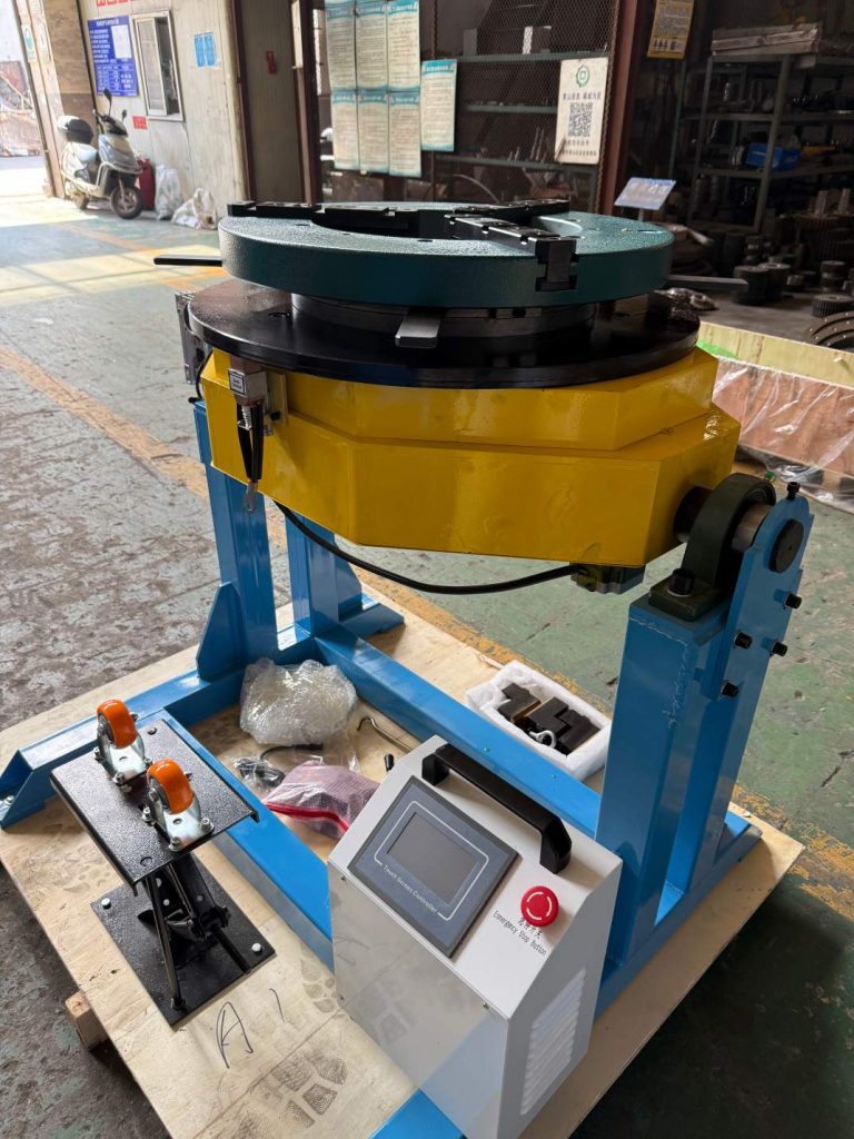
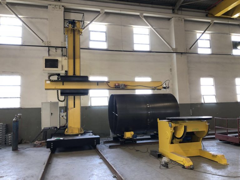
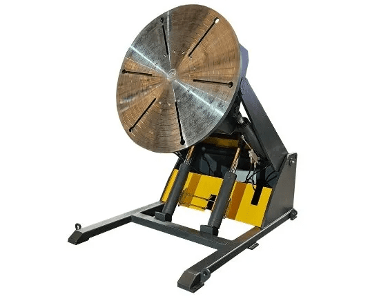
Positioning equipment can remove many undercut causes at the source. A welding positioner or rotator keeps the weld pool in a flat or horizontal location where gravity assists fill at the toes. This is especially useful for pipes, flanges, small vessels, and irregular workpieces that require rotating or tilting.
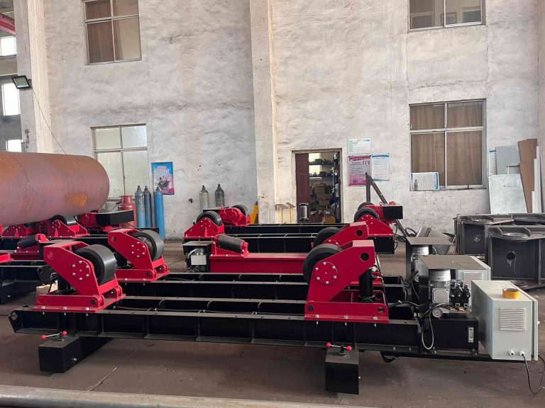
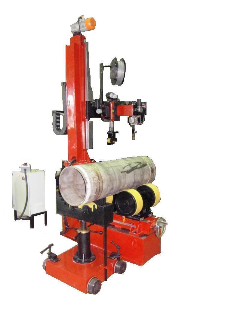
For cylindrical parts, a self-aligning welding rotator can maintain workpiece rotation while the operator holds a short, consistent arc. The operator is no longer required to crawl around the pipe or repeatedly reposition the body.
For long straight seams on large vessels or plate girders, a welding manipulator can maintain torch angle and travel speed more consistently than a manual hand track, reducing arc drift and undercut along the seam.
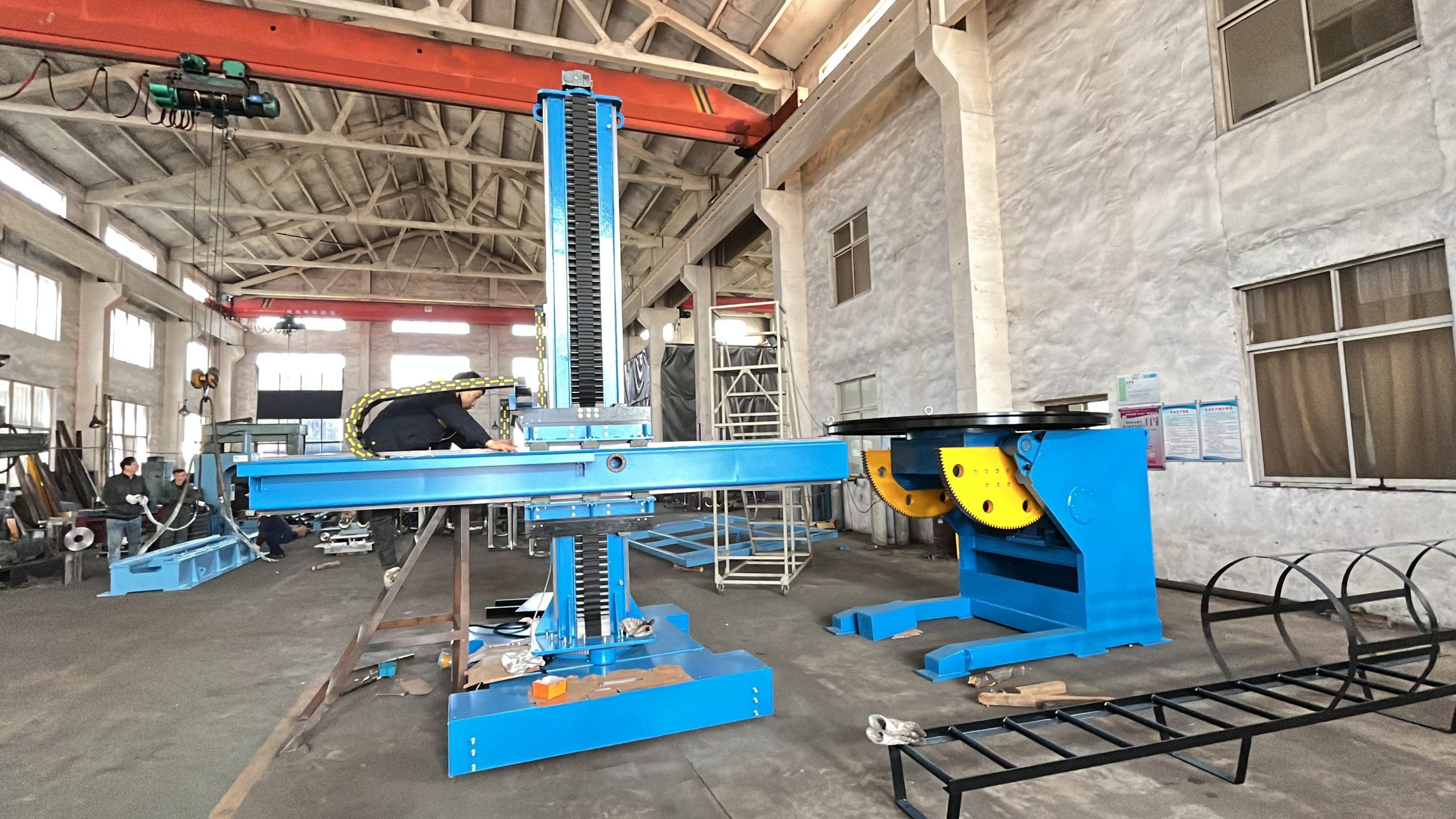
When the weld is held in a stable position and the operator is not fighting to maintain arc length, undercut becomes much easier to control. <Pipe Welding Rotator vs Manual Welding | Productivity and Cost Comparison> covers why rotating pipe instead of repositioning the operator produces more consistent travel angles.
Quick Corrective Actions for Repeat Undercut
| Observed Condition | First Corrective Action |
|---|---|
| Undercut on one side of a fillet weld only | Adjust work angle toward the undercut side |
| Undercut along the entire weld length | Reduce amperage or voltage slightly |
| Intermittent undercut at irregular spacing | Check travel speed and arc length consistency |
| Undercut at the end of a weld or around curves | Slow down and tighten the arc near position changes |
| Wide, flat bead with undercut at both toes | Reduce voltage or arc length and narrow the weave |
| Undercut only in out-of-position work | Use positioner or fixture to improve joint access |
Mid-Process CTA for Recurring Weld Defects
If your team is chasing repeat undercut across pipe or vessel joints, documenting the procedure and the exact welding position often reveals a positioning or parameter mismatch. You can send your current WPS, joint drawing, or macro photos to [email protected]. Keep the message practical: material and thickness, process, current and voltage, travel angle, and where the undercut appears.
Process stability is one of the strongest tools against weld toe defects. <Automatic Welding Centers Improve Production Efficiency & Weld Quality> covers how automated centers help welding teams hold parameters more consistently.
Inspection and Measurement of Undercut
Undercut is evaluated by measuring the depth from the original plate surface to the deepest point of the groove and by measuring the total length of the affected area [4][5].
A bridge cam gauge or pit gauge is commonly used for depth measurement. The gauge is placed across the weld so that its reference surface bridges the recessed area, and the depth indicator is lowered into the undercut groove [6]. The measurement should be taken at the deepest point of the defect, not just at the most visible edge.
Visual inspection is normally performed first, followed by gauge measurement when the undercut is close to the acceptance limit. For critical or fatigue-loaded structures, the inspector may also require liquid penetrant or magnetic particle testing to confirm that no crack is present at the undercut location.
Repairing Undercut That Does Not Meet Acceptance Criteria
When undercut exceeds the applicable code limit, it must be repaired before final acceptance. The repair approach depends on the material, weld size, and whether the undercut is shallow or deep.
Shallow undercut on carbon steel is often repaired by depositing a small stringer bead along the toe with lower heat input and a short arc. The repair pass should wet into the existing weld and base metal without creating a second undercut. For deeper undercut or hard-to-reach areas, light grinding may be required to open the groove before depositing the repair pass.
After repair, the area should be re-inspected and the repair weld should blend smoothly into the adjacent surfaces. In pressure equipment or coded work, all repairs should follow the repair procedure approved for the job.
If undercut is appearing on the same seam or joint every shift, the issue may be the setup rather than the welder. <Enhance Welding Productivity: 50% Efficiency Improvement> covers how small changes in procedure and equipment use can reduce rework.
End CTA: Get a Second Opinion on Your Welding Procedure
At WUXI ABK MACHINERY CO., LTD, we support welding automation, weld positioning, and CNC cutting lines. If undercut is tied to a hard-to-reach joint, unstable positioning, or an inconsistent manual travel path, contact [email protected] or +86 13616174307 with photos and a short description of the problem. We help fabricators separate operator technique issues from equipment or procedure issues.
FAQ
Is undercut always a welding defect?
Undercut is classified as a weld imperfection. Whether it is accepted depends on its depth, length, and the governing code or quality level [3][5]. A shallow undercut may be acceptable in some applications, while the same condition may require repair in a fatigue-loaded or pressure-retaining weld.
Can undercut be repaired by grinding alone?
Grinding can be used to remove a sharp notch, but it also reduces the plate cross-section. For undercut beyond the acceptance limit, the preferred repair is usually to grind or clean the groove and then deposit a small weld pass to restore the original contour [4].
Which welding processes are most prone to undercut?
Undercut can occur with most fusion welding processes. It is commonly associated with high-energy, high-deposition processes when parameters are not matched to the joint, but the root cause is usually arc force, travel speed, or torch angle rather than the process itself.
How is undercut depth measured?
A bridge cam gauge or similar weld-measuring instrument is placed across the undercut area, and the depth indicator is lowered into the deepest point of the groove [6]. The measurement is compared with the acceptance limit in the applicable code or specification.
Does changing polarity stop undercut?
Polarity affects arc behavior and heat distribution, but it is not a universal fix for undercut. Polarity changes should be made only after confirming the current, voltage, travel angle, and travel speed are correct for the base material and process.
What should be checked first when undercut keeps appearing?
Start with the weld pool shape. If the bead is wide and flat, check voltage and arc length. If undercut is one-sided, check work angle. If it appears in certain positions only, evaluate joint access and the possibility of using a positioner or manipulator to improve the orientation.
References
[1] American Welding Society, AWS A3.0M/A3.0:2020, Standard Welding Terms and Definitions, AWS, 2020.
[2] American Welding Society, Welding Handbook, Volume 1: Welding Science and Technology, AWS.
[3] International Organization for Standardization, ISO 5817:2023, Welding — Fusion-welded joints in steel, nickel, titanium and their alloys — Quality levels for imperfections, ISO, 2023.
[4] American Welding Society, AWS D1.1/D1.1M:2020, Structural Welding Code—Steel, AWS, 2020.
[5] International Organization for Standardization, ISO 6520-1:2007, Welding and allied processes — Classification of geometric imperfections in metallic materials — Part 1: Fusion welding, ISO, 2007.
[6] American Welding Society, Welding Inspection Technology, AWS.
If you’re interested, check out these related articles:
Automating Wind Tower Welding: Boost Productivity and Quality
Boiler Production Lines: Tube to Panel Manufacturing Explained
Tube to Tube Automatic Welding for Boiler Header Joints
CNC Water Jet Cutting: Precision, No Heat, Any Material