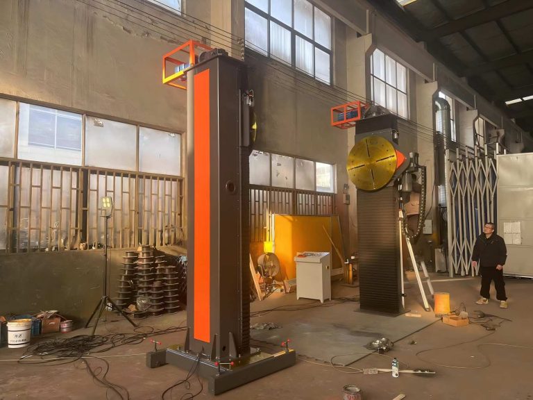
Spot Welding: Process, Parameters and Defect Control
Table of Contents
- How Does Spot Welding Work?
- Which Spot Welding Parameters Determine Weld Strength?
- How Do Electrode Force and Material Stack-Ups Affect Results?
- What Spot Welding Defects Should You Plan For?
- How Do You Select Spot Welding Equipment for Production?
- When Should You Contact a Spot Welding Equipment Supplier?
- What Production Teams Ask About Spot Welding
- What is the difference between spot welding and projection welding?
- Can spot welding join aluminum sheet in a production line?
- How often should spot welding electrodes be dressed?
- What information should you prepare before requesting a spot welding quotation?
Most spot welding failures I investigate are not machine failures. They happen because an electrode force target was never confirmed, a coating layer was ignored, or a weld schedule was copied from a different part family. Spot welding produces fast and repeatable sheet metal joints, but only when the parameters match the material stack-up, part geometry and production volume. A welder that runs well on bare cold rolled steel can drift badly on zinc coated stock. The sections that follow cover how spot welding works, which parameters decide weld strength, and how to evaluate equipment before it reaches your floor. The perspective comes from over twelve years of industrial welding automation work at ABOKE Machinery.
How Does Spot Welding Work?
Spot welding is a resistance welding process. Two copper alloy electrodes press the workpieces together, then a high current passes through the stack for a short time. Heat builds up at the interface where electrical resistance is highest, melting a small nugget that becomes the weld after force is held during solidification.
The weld cycle has four parts. Squeeze time closes the electrodes and builds force before current flows. Weld time applies current, usually for 50 to 500 milliseconds depending on material and stack thickness. Hold time keeps the electrodes closed while the nugget cools under pressure. Off time releases the electrodes and the next part moves into position. In automated sheet metal cells, a welding timer or a PLC integrated with the line manages these phases.
Current is normally in the range of 3 to 15 kA for thin sheet stacks, with open circuit voltage under 10 V on many machines. Because the voltage is low, secondary circuit resistance matters more than many people expect. Loose connections, worn cables, or a dirty electrode holder can shift heat away from the workpiece.
Which Spot Welding Parameters Determine Weld Strength?
Six parameters do most of the work in a stable spot welding setup. The table below shows what each one controls and what happens when it drifts.
| Parameter | What it controls | Too low | Too high |
|---|---|---|---|
| Weld current | Nugget size and heat input | Undersized nugget | Expulsion and electrode wear |
| Weld time | Heat soak and nugget growth | Cold, incomplete fusion | Distortion and surface damage |
| Electrode force | Contact resistance and forging | Arcing and erratic welds | Deep indentation and low heat |
| Squeeze time | Contact stability before current | Variable resistance | Unnecessary cycle delay |
| Hold time | Nugget solidification under pressure | Cracking risk | Lower throughput |
| Tip diameter | Current density at the part face | Low density, weak nugget | Expulsion at high current |
Weld current and electrode force should be treated as a pair. Increasing current grows the nugget, but only if force keeps the materials in contact. When force is too low, the stack expels molten metal early, and the weld surface becomes unpredictable. When force is too high, contact resistance drops, and the same current no longer generates enough heat.
How Do Electrode Force and Material Stack-Ups Affect Results?
Material stack-up is the variable I see most often underestimated. A two sheet stack of 0.8 mm cold rolled steel is forgiving. A three sheet stack that mixes 0.7 mm DC04 with 1.5 mm zinc coated steel is not. The outer layer, total thickness, coating type, and fit-up gap all change where heat concentrates.
Zinc coatings are the clearest example. Galvanized sheet requires a higher current than bare steel because zinc vaporizes and cools the interface, and the coating contaminates the copper electrode face faster. That raises contact resistance over the run and causes weld quality to shift after a few hundred parts. Production lines therefore need a defined tip dressing interval, not an operator judgment call.
Electrode force interacts with this. On coated steel, I normally begin with the same force as bare steel and increase it in small steps while watching indentation depth and expulsion. If the force is too low, the coating layer causes localized arcing before the interface melts. If the force is too high, the electrodes sink into a hot part. The correct force band is often narrower than the current band, and it changes when the stack height changes.
If your program involves galvanized steel or a three sheet stack, it is worth confirming the electrode force band and dressing interval before you lock the production sequence. Send your material stack-up to [email protected] and we will review it against your weld schedule.
What Spot Welding Defects Should You Plan For?
Spot welding defects fall into a short list, but each has a different root cause. Expulsion means molten metal leaves the joint during current flow. It looks like sparking at the electrode face and leaves a crater and reduced weld size. Undersized nuggets are worse because the part may look acceptable but fail peel or shear testing. Indentation, burn-through, and hot cracking complete the set most shops see.
One failure mode deserves more attention than it usually gets: intermittent undersized nuggets from electrode wear. I traced this on a line where a mushroomed tip had grown from 5 mm to roughly 7 mm in diameter. The contact area increased and current density fell. Parts passed visual inspection because the indentation was barely visible, but peel testing showed weld separation on nearly every second part. The fix was mechanical tip dressing on a scheduled count rather than waiting for an operator to notice.
How Do You Select Spot Welding Equipment for Production?
Buyers often compare machines by kVA rating and stop there. kVA tells you the transformer capacity. It does not tell you whether the secondary circuit, electrode holders, and cooling system can maintain that output over an eight-hour shift. For high-volume lines, water cooled electrodes and a low impedance secondary loop matter more than a large nameplate number.
AC machines are simpler and less expensive. Medium frequency direct current (MFDC) systems use a smaller transformer, draw less peak current, and control heat more evenly on coated or high strength steel. The trade-off is cost and complexity. I recommend MFDC when the part family includes galvanized steel, aluminum, or more than two thickness combinations. AC remains a practical choice for simple mild steel parts with stable stacking.
Controls are the next cut. A basic timer is enough for a dedicated cell making one part. For mixed production, look for a controller that stores multiple weld schedules, monitors current and force, and confirms each pulse against a window. That data becomes the difference between finding a process drift in one shift and discovering it during a customer audit months later.
Surface condition also affects spot welding more than many fabricators expect. Heavy mill scale or rust changes contact resistance, so lines that process such stock often use an upstream 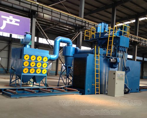 to clean the surface.
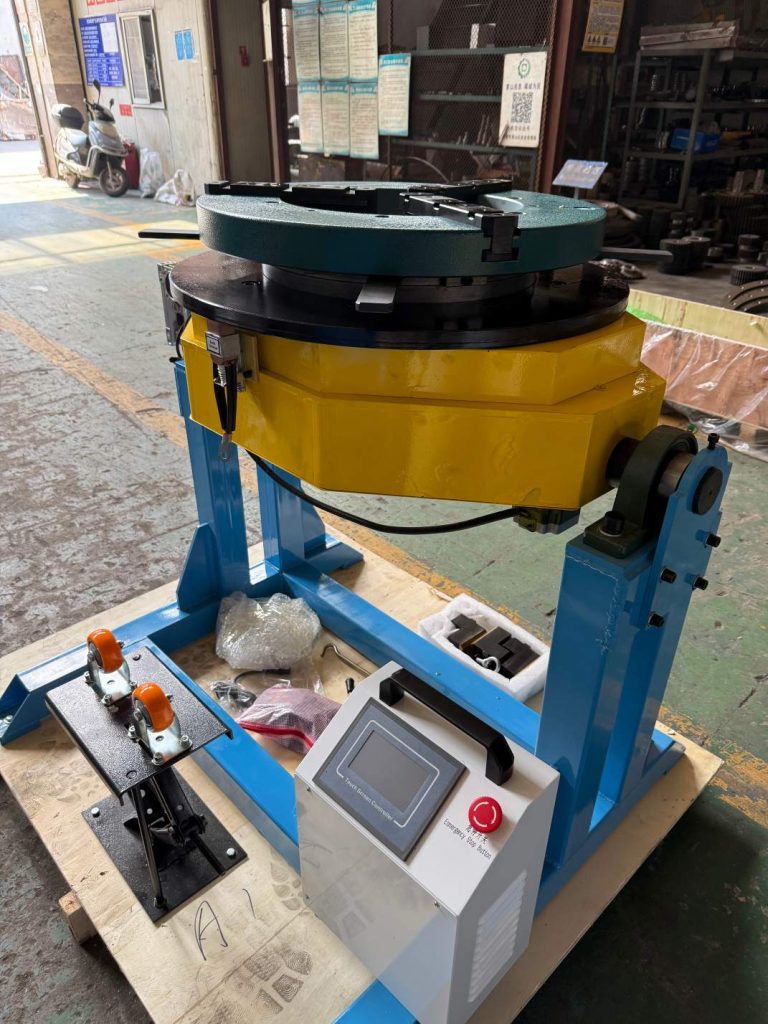
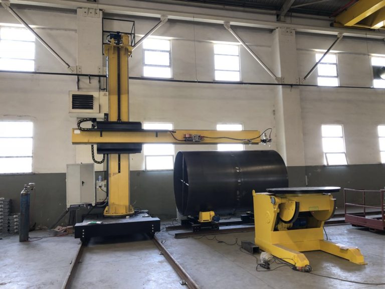
For fixture-intensive cells, ABOKE Machinery also supplies positioning and handling components such as the 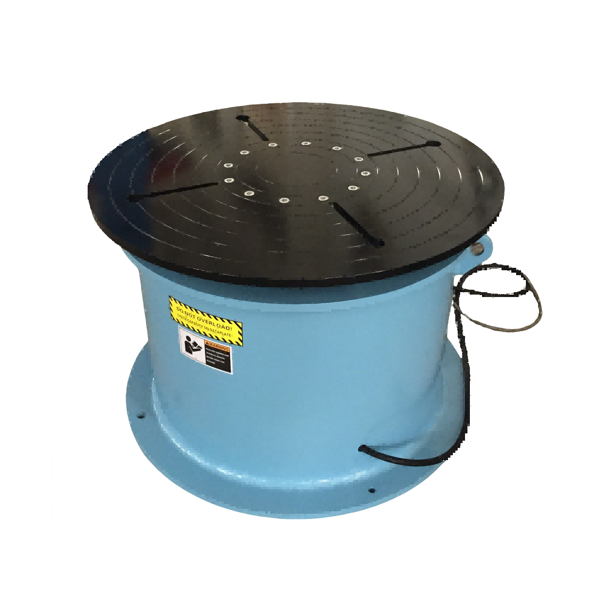 and
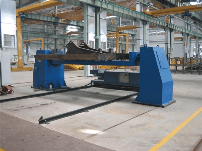 for secondary welding and subassembly handling.
When Should You Contact a Spot Welding Equipment Supplier?
Most quotation requests skip the two details that determine whether a spot welding proposal will work: the exact material stack-up and the target production rate. Without them, a supplier can only quote a standalone machine, not a production cell that holds quality over a full shift.
ABOKE Machinery approaches spot welding projects the way we approach automated welding lines. We first look at the part family, coating condition, changeover frequency, and downstream operations. Then we confirm the machine configuration, electrode cooling method, control requirements, and fixture concept before quoting.
Send your part drawings, material grades, stack-up sequence, and target parts per hour to [email protected] or call +86 13616174307. We will confirm which spot welding configuration fits your line and what tooling you should plan for.
What Production Teams Ask About Spot Welding
What is the difference between spot welding and projection welding?
Spot welding joins sheets through electrodes that contact a relatively flat surface. Projection welding uses small raised features on one part to concentrate current at defined points. That makes projection welding useful when multiple welds must form in one cycle or when one side of the assembly has a thin or delicate surface. For flat sheet stacks, spot welding remains the simpler and faster option.
Can spot welding join aluminum sheet in a production line?
Many shops assume aluminum cannot be spot welded, but it can. The real issue is that aluminum has low electrical resistance and high thermal conductivity, so it needs much higher current and shorter weld time than steel. Electrode wear is also more demanding because aluminum tends to stick to copper electrodes. MFDC controls and proper tip dressing become important. For mixed steel and aluminum lines, each material family should have its own confirmed schedule rather than a shared setting.
How often should spot welding electrodes be dressed?
It depends on the coating, current level, and production volume. Bare mild steel may run for several hundred parts before noticeable wear, while galvanized steel forms zinc oxide on the tip and can require dressing after a much shorter interval. The more useful practice is to set a part count or production time trigger and inspect the first few nuggets after dressing. This keeps the process stable before visual defects appear.
What information should you prepare before requesting a spot welding quotation?
Rather than ask for a generic spot welder, send the material stack-up first. The grade, thickness, coating, number of layers, and target parts per hour determine the current range, force requirement, cooling method, and control features. Missing coating information is the most common reason a quotation looks right on paper but fails on the floor. Share these details with [email protected] and we will confirm which spot welding configuration and fixture concept fits your part family.
If you’re interested, check out these related articles:
Heavy-Duty Welding Rotators with 200 Ton Load Capacity
Welding Positioner Selection for Pressure Vessels: Key Best Practices
Wind Tower Welding Lines: Designing for Peak Production