GMAW MIG Welding Explained: How It Works and When to Use It
Table of Contents
- What GMAW MIG Welding Is and Why the Arc Self-Regulates
- Transfer Modes Decide the Weld More Than the Settings Do
- Matching Shielding Gas and Wire to the Steel
- What GMAW Delivers and What It Costs You
- Where GMAW Fits and Where It Does Not
- How Positioning Changes GMAW Results
- Setting Up a Station That Stays Repeatable
- Qualifying the Procedure Before Production Starts
- What to Send Before You Choose the Process
- FAQ
- Is MIG welding the same as GMAW?
- Can GMAW be used outdoors?
- What plate thickness suits GMAW?
- Why does my MIG bead sit high and lumpy?
- References
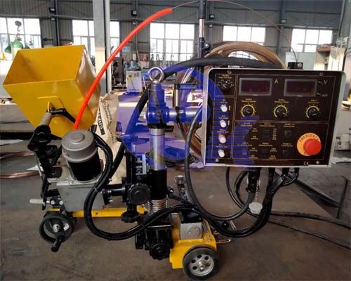
GMAW MIG welding is a continuous-wire arc process. A solid electrode feeds through a gun into the joint, an arc burns between the wire and the workpiece, and a shielding gas keeps the atmosphere out of the puddle. The gas is not what makes the process productive. The feed is. Because the wire never stops for an electrode change, and because wire feed speed rather than rod diameter sets the current, one machine covers sheet metal and heavy fillets with only the settings and the transfer mode changing. That flexibility is also where most trouble starts, since the settings interact and a change in one moves the others.
What GMAW MIG Welding Is and Why the Arc Self-Regulates
Every GMAW setup holds the same four elements: a power source, a wire feeder with a gun and contact tip, a solid wire electrode, and shielding gas delivered through a nozzle. The wire is both electrode and filler metal, so the arc starts once per joint instead of once per rod.
The control that makes the process work is constant voltage. The machine holds a set voltage while wire feed speed decides how much current flows. Push more wire into the arc and it burns off faster only because current rises, so the system settles where burn-off matches feed rate. That is the self-regulating arc, and it produces the practical rule most experienced operators follow: voltage sets arc length, wire feed speed sets current. An operator who turns the voltage dial to change penetration is working against the machine’s design, and the bead usually shows it.
GMAW runs electrode positive as standard. The workpiece takes the larger share of the arc energy, which is where the process gets its penetration on a joint that has been fitted properly.
Contact tip to work distance is the variable that quietly changes everything else. The length of wire between the tip and the arc is resistance-heated, so a longer stickout reduces current at the same feed setting and spreads the gas stream. Most shops treat stickout as a habit rather than a setting, which is why two operators on one machine can produce visibly different beads from the same parameter sheet. Measure it, write it on the work instruction, and the argument about “the machine running cold” usually ends.
Duty cycle matters too, and not in the way new buyers expect. A duty cycle is rated over a ten-minute period, so a 60% rating at a stated current allows six minutes of arc in every ten. Exceed the current and the rating falls, which is why a machine that welds all day at 250 A needs a different frame size than one that welds in short bursts.
Transfer Modes Decide the Weld More Than the Settings Do
Molten metal crosses a GMAW arc in one of four ways, and the mode shapes bead profile, spatter level, position capability and heat input more than small dial adjustments do. The mode is set by current density, wire diameter, shielding gas and voltage together, not by a single switch.
| Transfer mode | How metal crosses the arc | Setting character | Best fit | Main risk |
|---|---|---|---|---|
| Short circuit | Wire contacts the puddle and pinches off, many times per second | Low voltage, low wire feed speed | Thin sheet, root passes, out-of-position work | Cold lap where the puddle freezes before the next touch |
| Globular | Large droplets detach under gravity | Middle current, above short circuit and below the spray transition | Flat joints on thicker plate where spatter can be cleaned | Heavy spatter, harsh arc, poor position control |
| Spray | Fine droplets stream axially from a tapered wire tip | High current with an argon-rich gas | Flat and horizontal fillet and butt work at high deposition | Heat input and distortion climb with deposition |
| Pulsed spray | Peak current detaches one droplet, background current keeps the arc alive | Intermediate average current, pulse parameters set on the machine | Out-of-position work and thinner sheet with spray-like finish | Synergic programs must match the wire and gas actually in use |
Short-circuit transfer is not simply low-power GMAW. Each short circuit quenches and restarts the arc, so the workpiece sees rapid heating and cooling cycles. On thin sheet that limits distortion and makes vertical work possible. On thicker plate it can leave cold lap, because the puddle freezes before the next wire touch arrives and the two never fuse.
The step from globular to spray depends on current density and gas. An argon-rich mixture supports a true spray arc at sufficient current. Straight carbon dioxide does not reach spray transfer at any current, which is a large part of why CO2 work looks and sounds different from mixed-gas work.
Matching Shielding Gas and Wire to the Steel
Shielding gas does three jobs at once: it excludes nitrogen and oxygen, it stabilises the arc, and it sets the transfer behaviour. For carbon steel, argon mixed with 15 to 25% carbon dioxide is the common choice. Raising the CO2 share deepens penetration and lowers gas cost, at the price of a rougher arc and more spatter. Straight CO2 is the cheapest option and the harshest to run. Stainless steel usually runs on an argon mix with a small oxygen or CO2 addition to keep the arc stable and the bead fluid. Aluminium runs on pure argon, with helium added for thicker sections where more heat is needed.
Solid wire selection follows the base metal and the surface condition, not the machine. AWS A5.18/A5.18M:2017 classifies carbon steel solid electrodes, and its designations decode directly: electrode, minimum tensile strength of the deposited weld metal in ksi, solid wire, and a classification number for chemistry [1]. ER70S-6, for example, is a solid wire with 70 ksi minimum tensile strength, and the “6” carries higher silicon and manganese than ER70S-3.
That difference matters on real plate. ER70S-6 tolerates mill scale and light rust because its deoxidizers handle the oxygen those contaminants introduce. ER70S-3 suits clean, freshly prepared steel. ER70S-2 adds stronger deoxidizers for root passes on pipe where the back of the joint is exposed to air. A classification listing tells you what the wire is, not what your joint will do with it, so a wire change still needs the procedure and the test results to agree.
Wire diameter sets where the useful current range sits. A smaller wire reaches spray transfer at a lower current because current density is higher, which helps on thin material and on out-of-position work. A larger wire carries more current without feeding problems, which helps on thick plate and long production runs.
What GMAW Delivers and What It Costs You
The productivity case rests on arc time. A stick welder stops to change electrodes, re-strike, and chip slag, so a large share of the shift goes to handling rather than welding. GMAW keeps the arc lit for the length of the joint, and the filler is consumed almost completely.
The other advantages are practical rather than dramatic. There is no flux to store, recover, or bake, which simplifies consumable control on site. Solid wire with clean gas produces low-hydrogen welds, which matters on steels where hydrogen cracking is a risk. The process is also the easiest arc process to automate, because wire feed and travel speed are both machine variables and no flux handling sits between the torch and the joint. Most robotic arc cells are built around a GMAW torch for this reason.
The costs are equally real. Shielding gas is a consumable with a supply chain, and it fails in moving air. The equipment chain is longer than a stick set: feeder, liner, drive rolls, gun, contact tip and nozzle all wear and all affect the arc. Wire feeding is a genuine constraint on soft wires such as aluminium, which buckle between the drive rolls and the tip unless the torch is short, the liner is right, and the drive rolls are the correct profile. Fume generation is continuous, so extraction has to be planned into the station rather than added afterwards.
The tradeoff is worth stating plainly. GMAW wins when the joint is long enough for the arc to stay lit and when the position lets the process run in an efficient mode. On a short repair in bad access, with the part still bolted in place, a stick welder and a generator still win, and no amount of parameter tuning changes that.
Repositioning work so the arc stays in one favourable orientation changes how much of a shift goes to welding rather than setup. <Enhance Welding Productivity: 50% Efficiency Improvement> covers the productivity case behind that figure.
Where GMAW Fits and Where It Does Not
Fabrication work divides along deposition, position and access. GMAW dominates thin to mid-thickness sheet and plate, long straight or circumferential runs, and any cell that will be automated. Structural steel, automotive frames, sheet metal enclosures, pipe spools and general job-shop work all sit inside its range.
| Process | Electrode | Shielding | Position freedom | Cleanup | Where it wins |
|---|---|---|---|---|---|
| GMAW | Continuous solid wire | Gas only | Flat and horizontal in spray, all positions in short circuit | Silicate islands and spatter only | Sheet to mid plate, long runs, automated cells |
| FCAW | Continuous tubular wire with a flux core | Gas shielded or self-shielded | Good in all positions, especially self-shielded | Slag removed between passes | Field work, wind, thicker sections, higher deposition |
| SMAW | Coated stick, fully consumed | Gas and slag from the coating | All positions | Slag chipping after every pass | Repair, poor access, low equipment cost |
| SAW | Continuous wire under a flux blanket | Granular flux | Flat and horizontal only | Flux and slag recovery | Long straight seams on thick plate at high deposition |
The boundaries appear at thickness and at wind. As plate thickness climbs, bevel preparation, preheat and pass count all climb with it, and the economics move toward processes built for deep, long seams. Submerged arc takes the straight longitudinal and circumferential seams on heavy shells. Vertical seams in large storage tanks are usually welded with electrogas or electroslag, where the weld is made in one pass up a prepared gap and the tooling carries the puddle.
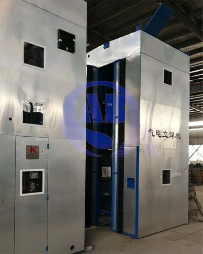
Field work is the other boundary. Moving air displaces the gas shield long before the operator notices anything wrong with the flow reading at the regulator, and the result is scattered porosity that no setting change will fix. Screens work around a fixed station. Where screens cannot be built, self-shielded flux-cored wire is usually the honest answer rather than a losing fight with gas coverage.
Pressure vessel work sits at the edge of the range. A vessel mixes thin nozzle welds with heavy shell courses on the same job, so the workholding has to be selected for the whole range rather than the average part.
Pressure vessel work mixes thin nozzles with heavy shell courses on the same job, so the workholding has to be chosen for the range rather than the average. <Welding Positioner Selection for Pressure Vessels: Key Best Practices> covers how the selection criteria change with vessel size and joint type.
How Positioning Changes GMAW Results
Gravity is the constant in every weld. A puddle that is too large for its position sags before it freezes, so the current a joint can carry depends on where that joint sits in space. Flat work tolerates more current, more deposition and a smoother bead than vertical or overhead work on the same thickness.
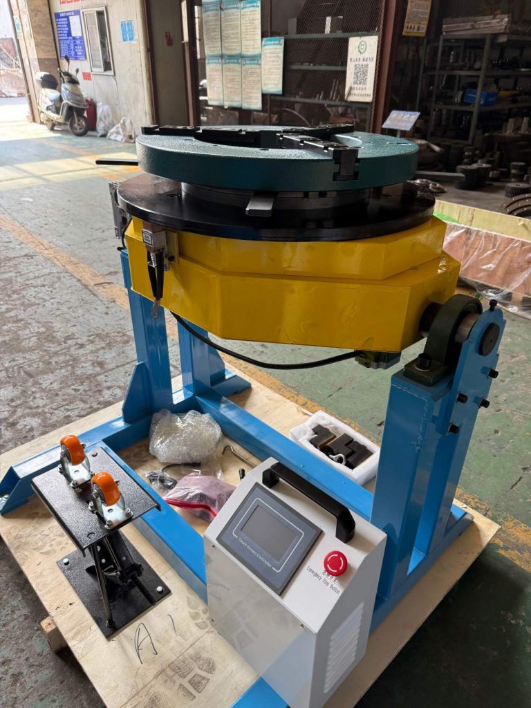
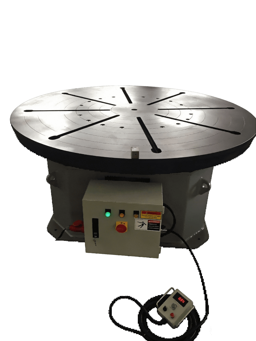
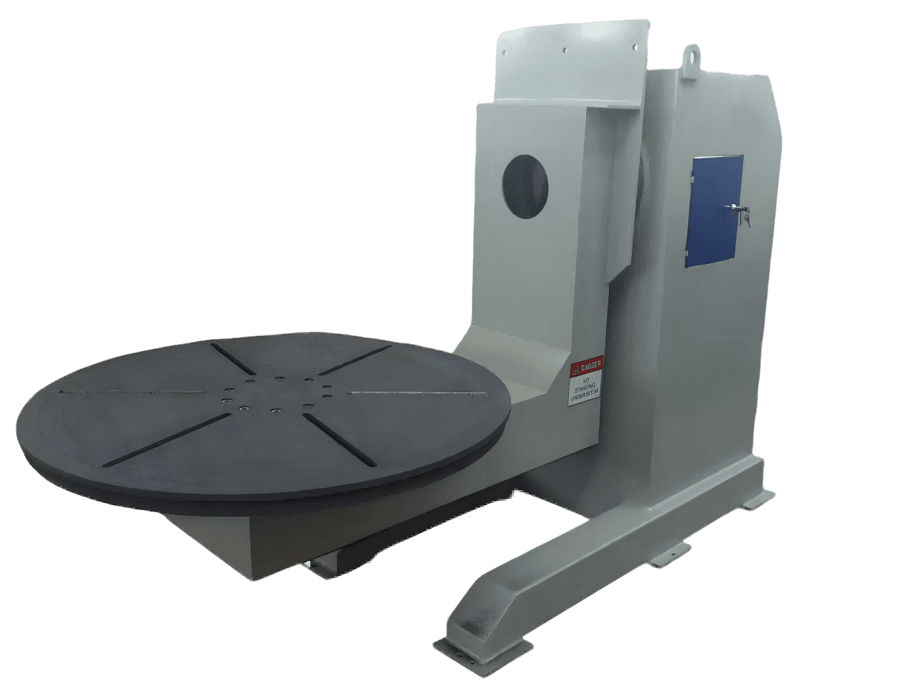
This is why positioners are not a convenience item in GMAW production. They let the operator keep the weld in one favourable orientation while the machine does the turning. For circumferential work, the usual arrangement is a rotator or turntable turning the shell while the gun stays at a fixed clock position, slightly off top dead centre, so the bead is supported by the metal that solidified behind it.
Shaft and pipe work needs a different axis. A head and tail positioner holds the workpiece between centres and rotates it about its own axis, which keeps runout predictable and keeps the seam at the same point through the whole revolution.
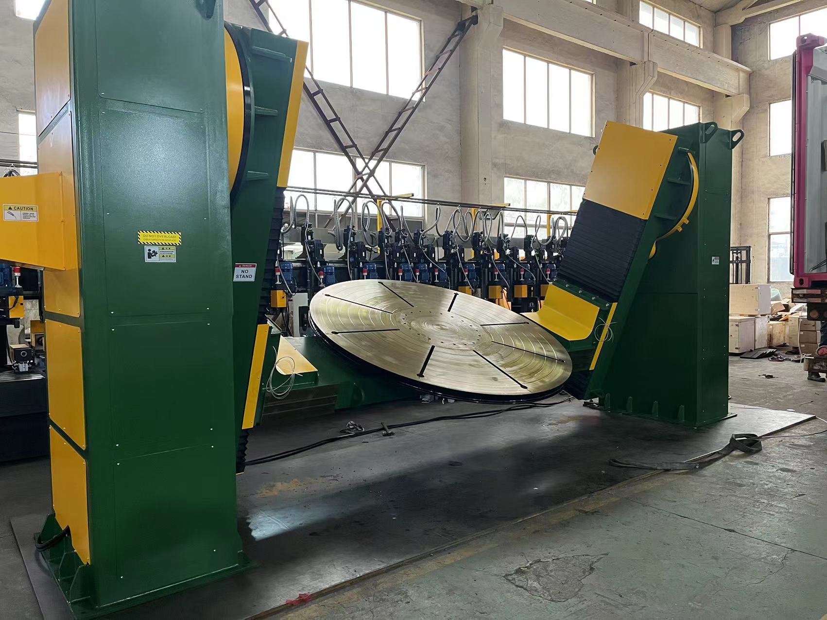
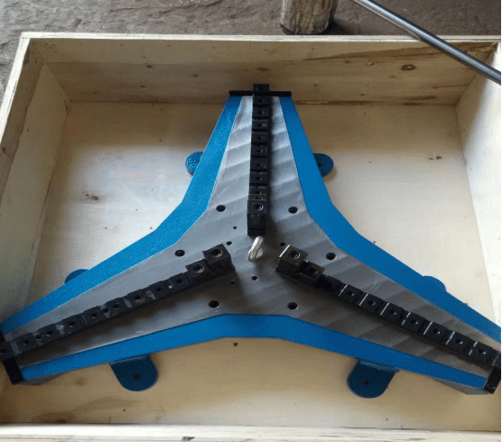
Frames, brackets and asymmetric fabrications need orientation rather than pure rotation, because the joint that must be flat is rarely aligned with the part’s centre of gravity.
Compound-angle parts need more than one axis of adjustment, so the operator can bring each joint into position in sequence without re-clamping the workpiece between passes.
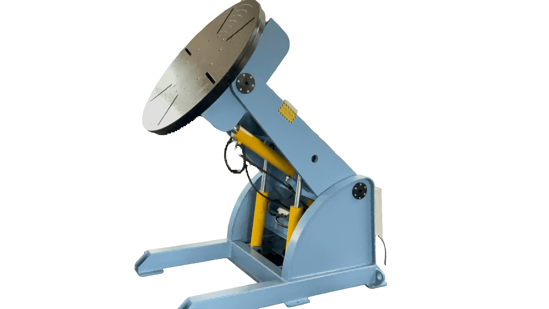
Equipment such as the positioners and rotators built by WUXI ABK MACHINERY CO., LTD exists to hold those three variables steady: orientation, rotation speed and repeatability. The selection questions stay the same whoever supplies the machine. Confirm the load rating against the workpiece plus fixture weight, not the workpiece alone, and check the offset load separately because a heavy part mounted away from the table centre produces a tilting torque the nominal rating does not describe. Confirm the rotation speed range covers the travel speed the weld needs, since a turntable that cannot run slowly enough is as limiting as one that cannot run fast enough. Confirm the work return cable clamps directly to the workpiece, because running welding current through the positioner’s bearings and structure is a known way to damage both.
Rotating a shaft or pipe spool so the seam stays at the same point is the difference between a consistent bead and a fight with gravity. <Precision Positioning for Pipe and Shaft Welding Workpieces> covers the workholding side of that problem.
Setting Up a Station That Stays Repeatable
A GMAW station drifts because several small components wear at once. The pre-start check takes a few minutes and catches most of it:
- Set gas flow at the cup with a flowmeter, not at the regulator gauge, and confirm the nozzle is clean and the correct size for the joint.
- Check the contact tip bore and the liner. A worn tip lets the wire wander and the arc follows it.
- Match drive roll profile and tension to the wire. Aluminium needs a U-groove roll and light tension, or it deforms and jams.
- Confirm polarity, work return clamp position near the joint, and that the return path is symmetric about the weld.
- Position fume extraction at the arc, not across the shop, and complete the hot work permit and fire watch before the first arc.
Ventilation and fire prevention are not optional refinements. OSHA 29 CFR 1910.252 sets the general requirements for welding operations in general industry, including ventilation and fire prevention measures that apply to GMAW as much as to any other arc process [2].
When something does go wrong, the fastest route is to work from symptom to cause rather than from the dial.
| Symptom | Check first | What the result tells you |
|---|---|---|
| Clustered porosity | Gas path | Nozzle spatter, flow at the cup, hose and regulator leaks, then drafts across the joint |
| Spatter that will not clear | Transfer mode | If the arc is globular, raise current into spray or switch to pulsed |
| Burn-through on thin sheet | Heat input | Wire feed speed, travel speed, joint gap, and whether short circuit is the better mode |
| Lack of fusion on a thick fillet | Aim and heat | Whether the wire points at the joint root, the travel angle, and the current against the qualified range |
| Wire stubbing and burn-back | Consumables and stickout | Contact tip bore wear, liner condition, and contact tip to work distance |
| Arc wandering on heavy steel | Work lead return | Ground clamp position and whether the return path is symmetric about the joint |
Qualifying the Procedure Before Production Starts
A parameter sheet that produces a good bead is not the same thing as a qualified procedure. Where a code applies, the welding procedure is qualified by test and the welders are qualified against it, and both records have to exist before production welding starts.
ISO 15614-1:2017 covers procedure qualification by welding procedure test for arc and gas welding of steels, and it defines the range of thickness, position and material each test supports [3]. Welder qualification follows a separate route, ISO 9606-1:2012 for fusion welding of steels, which tests the person rather than the procedure [4]. Structural steel work in the United States usually falls under AWS D1.1/D1.1M:2020, which sets its own requirements for procedure qualification, welder qualification, and inspection [5].
The essential variables are where GMAW procedures get caught out. A change from short circuit to spray transfer, a change from mixed gas to straight CO2, a different wire classification, a thickness outside the qualified range, or a change in welding position can each take the procedure outside its qualification. A qualification test proves the procedure produced an acceptable test piece under the conditions tested. It does not prove that the same wire will behave the same way at twice the thickness or in a different position, and assuming otherwise is how a compliant shop ends up with a repair rate it cannot explain.
What to Send Before You Choose the Process
Tell us the base metal and thickness, joint design and root gap, welding position, the transfer mode you intend to run, your power supply, and the annual meterage or unit count. Those details decide whether the joint suits GMAW at all, what the wire and gas should be, and how much workholding or rotation the job needs before the first pass.
[email protected]
+86 13616174307
WUXI ABK MACHINERY CO., LTD
FAQ
Is MIG welding the same as GMAW?
MIG is one form of GMAW. The formal name covers any gas metal arc process using a continuous wire and an external shielding gas. MIG refers to an inert shielding gas, typically argon or helium, which is what aluminium and much stainless work uses. MAG refers to an active gas such as a carbon dioxide mix, which is common on carbon steel. In North America “MIG” is used loosely for both, so when a specification matters, check the gas named on the procedure rather than the label on the machine.
Can GMAW be used outdoors?
Only where the operator controls air movement across the joint. The gas shield is easily displaced, and the failure shows up as porosity rather than as an obvious change in the arc. Fixed outdoor stations can use wind screens. Field work on pipe racks or structural steel usually suits self-shielded flux-cored wire better, because the shielding is generated by the wire rather than supplied from a bottle.
What plate thickness suits GMAW?
GMAW covers thin sheet through mid-thickness plate comfortably, with short-circuit transfer on the thin end and spray transfer for deposition on the thicker end. The practical limit is economic rather than absolute. As thickness rises, bevel preparation, preheat and pass count rise with it, and long heavy seams are usually handed to submerged arc or electrogas, while GMAW takes the root, the shorter joints, and the fabrication around them.
Why does my MIG bead sit high and lumpy?
A high, rope-like bead usually means heat input is low for the travel speed, or the arc is sitting in globular transfer. Check wire feed speed and voltage against each other, measure contact tip to work distance, confirm the gas is the one the settings assume, and look at travel speed. If the machine is running below the spray transition, the arc will sound harsh and throw spatter, which is the clue that the mode rather than the operator is the problem.
References
[1] AWS A5.18/A5.18M:2017, Specification for Carbon Steel Electrodes and Rods for Gas Shielded Arc Welding. American Welding Society, 2017.
[2] OSHA, 29 CFR 1910.252, General requirements, Welding, Cutting, and Brazing. Occupational Safety and Health Administration, U.S. Department of Labor.
[3] ISO 15614-1:2017, Specification and qualification of welding procedures for metallic materials. Welding procedure test. Part 1: Arc and gas welding of steels and arc welding of nickel and titanium. ISO, 2017.
[4] ISO 9606-1:2012, Qualification testing of welders. Fusion welding. Part 1: Steels. ISO, 2012.
[5] AWS D1.1/D1.1M:2020, Structural Welding Code, Steel. American Welding Society, 2020.
If you’re interested, check out these related articles:
Welding Manipulators for Storage Tanks: Girth and Seam Automation
One-Stop Welding Automation: Build a Complete Production Line Setup
Shot Blasting Solutions for Steel Structure Surface Treatment
Wind Tower Welding Lines: Designing for Peak Production