Steel Tank Construction: Process, Equipment and Checks
Table of Contents
- What steel tank construction covers and which standard governs
- How the build sequence runs from plate to hydrostatic test
- When shop fabrication beats field erection
- Where ovality and weld repair come from
- Matching welding equipment to each construction stage
- Welding and inspection steps that prove the tank
- How the weld sequence is set
- When post-weld heat treatment is required
- What each inspection test proves
- What to fix in the RFQ before the first plate is cut
- Match the equipment package to your tank data
- FAQ
- How long does steel tank construction take?
- What is the difference between API 650 and ASME Section VIII?
- Is hydrostatic testing required for every tank?
- Why does the shell-to-bottom junction leak more often than shell seams?
- Can a large tank be fully shop fabricated?
- References
Steel tank construction is the sequence of plate preparation, forming, fit-up, welding and testing that turns flat steel into a liquid-tight shell, and the standard named in the contract decides how much of that sequence is inspected, how thick the shell must be, and who signs the release. Two tanks with identical dimensions can carry very different cost and schedule profiles once API 650, EN 14015 or ASME Section VIII governs the work. The decisions that set the outcome come before the first production weld: standard scope, shop or field erection, and the tolerance band held during shell fit-up.
What steel tank construction covers and which standard governs
The phrase covers at least three families of work that share equipment and skills but not acceptance rules. Field-erected atmospheric storage tanks follow API 650. Large welded tanks designed for low internal pressure and low-temperature service follow API 620. Pressure vessels, including many shop-built tanks that operate above atmospheric pressure, follow ASME Boiler and Pressure Vessel Code Section VIII. European projects with the same geometry as an API 650 tank usually specify EN 14015 instead. Once the tank exists, in-service inspection and repair move to API 653.
| Standard | Typical scope | What it controls |
|---|---|---|
| API Std 650 | Field-erected, vertical, cylindrical, atmospheric tanks | Shell design, materials, joint efficiency, hydrostatic testing [1] |
| API Std 620 | Large welded tanks for low internal pressure and low temperature | Design rules for pressure and low-temperature service [2] |
| ASME BPVC Section VIII, Division 1 | Pressure vessels and tanks above atmospheric pressure | Rule-based design, joint efficiency, post-weld heat treatment, NDT extent [3] |
| EN 14015:2004 | Site-built vertical cylindrical tanks for liquids near ambient temperature | European design and manufacturing requirements [4] |
| API Std 653 | Tanks already in service | Inspection, repair, alteration and reconstruction [5] |
The choice is commercial as well as technical, because the standard fixes the credit given for radiography. In ASME Section VIII Division 1, a double-welded butt joint earns a joint efficiency of 1.00 with full radiography, 0.85 with spot radiography and 0.70 with none [3]. Joint efficiency multiplies the allowable stress in the thickness calculation, so reducing radiography saves inspection hours and adds shell thickness, steel weight and welding hours. On a large shell that trade is rarely free in either direction, and it belongs in the contract rather than in a conversation after the plates are ordered.
How the build sequence runs from plate to hydrostatic test
The stages are the same whether the tank is built in a shop bay or on a foundation:
- Plate cutting and edge preparation.
- Shell course rolling.
- Bottom layout and welding.
- Shell erection and fit-up of each course.
- Longitudinal and girth seam welding.
- Roof, nozzles and appurtenances.
- Inspection and hydrostatic testing.
Cut quality matters more than it looks, because on most shell plates the cut edge becomes the weld preparation. A square, dross-free edge with the specified bevel lets the root gap be set by fit-up. A ragged plasma edge, or a bevel cut at the wrong angle, forces the welder to close the gap with deposited metal, which changes penetration, heat input and distortion at the same time.
Plate edges cut for a shell course become the weld preparation, so squareness and bevel consistency carry straight into root gap control. <CNC Flame Cutting: Precision Cutting for Heavy Plate Fabrication> covers precision cutting practice for heavy plate fabrication.
Where the cut face will also be the weld face and heat input is a concern, a cold process removes the heat-affected zone from the edge entirely. Waterjet cutting is slower per metre than plasma on thin plate and becomes competitive on thick plate where the edge needs no further dressing before welding.
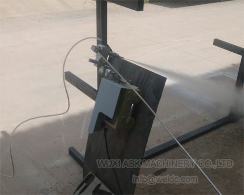
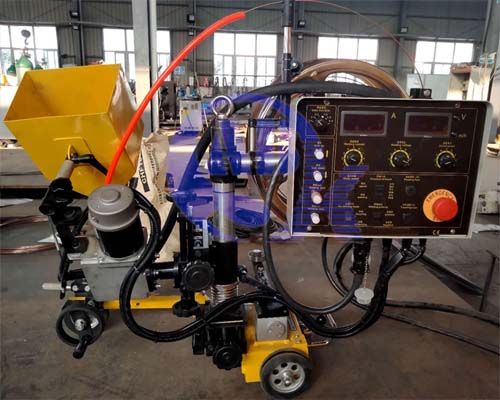
Bottom plates are welded flat, which allows long continuous runs with a gantry or tractor-mounted head and reduces the stop-start that leaves craters at plate joins. Bottom shrinkage pulls the shell inward at the base, so the bottom weld sequence is planned before the first shell course is set, not after.
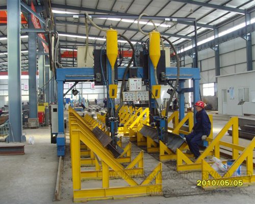
Erection then splits into two routes. In bottom-up erection, courses are lifted into place by crane and welded as they go. In the jacking method, the roof and top course are assembled at grade, jacked up, and the next course is added underneath. Jacking keeps most welding near the ground and cuts work at height, at the cost of jacking equipment, a temporary stability check and a lift plan that has to be followed in order.
When shop fabrication beats field erection
Transport usually settles it. If the shell fits inside the shipping envelope and the site cannot support erection at height, shop fabrication keeps welding in flat and horizontal positions, keeps inspection and rework under one roof, and removes weather from the schedule. If diameter or weight exceeds what can be moved, plates are cut and rolled in a shop and welded on site, which is the common hybrid rather than a truly field-fabricated tank.
| Criterion | Shop fabrication | Field erection |
|---|---|---|
| Size limit | Bounded by the road or sea freight envelope | Bounded by site access and crane capacity |
| Weld position | Mostly flat and horizontal, suited to submerged arc welding | Vertical and overhead work increases |
| Inspection access | Stable, covered, one crew and one record set | Weather-dependent, more scaffolding and access work |
| Schedule risk | Transport and lifting, low weather risk | Wind, rain and temperature affect welding |
| Cost driver | Shop hours and freight | Site labour, scaffolding, crane time |
| Correction of errors | Re-rolling and re-machining available | Limited to cutting out and re-welding |
One detail buyers miss in the hybrid route: curved courses that travel well are not automatically round when they arrive. Support cradles, lifting points and stacking practice decide how much ovality the plates pick up in transit, and that ovality is added to whatever the rolls produced.
Where ovality and weld repair come from
Ovality is not created at the last course; it accumulates from the first. Call the tolerance band held during shell assembly the fit-up window. It is the range of root gap, radius deviation and plumbness the welding stage can absorb without correction. Once a course falls outside that window, no welding sequence recovers it. The error is redistributed around the next girth seam as variable gap, and variable gap is the usual source of repair.
Two mechanisms do most of the damage. The first is circumference error from rolling, which appears as mismatch at the longitudinal seam and is carried upward. The second is support geometry: a shell resting on two rolls flattens slightly between the contact points, and thin shells deflect more than thick ones. Roll width, roll spacing and load per roll decide how much of that deflection survives into the girth seam.
Rotator alignment matters for the same reason. If the drive unit and the idler unit are out of line, the shell drifts axially as it turns, and the girth seam wanders instead of staying in one plane. The seam then needs correction, and correction means more weld metal, more heat and more distortion.
Practical checks that catch this early:
- Measure circumference at the top and bottom of each course before fit-up and record the difference.
- Measure radius deviation at a fixed set of stations around each course, using the same stations every time so the trend is visible.
- Check rotator units for level and centre distance before the first turn, then recheck once the shell is loaded.
- Compare plumbness against the tolerance in the governing standard rather than against what looks straight on site [1].
Fit-up decides how much of the circumference error the welding stage has to absorb, and an alignment rotator keeps that decision under control before the first girth seam is made. <Fit-Up Rotator for Accurate Vessel Alignment & Stable Welding> covers vessel alignment and weld stability during fit-up.
Matching welding equipment to each construction stage
Equipment choice follows weld position and access, not catalogue size. The table below maps each stage to the equipment that actually changes the result.
| Stage | Equipment that decides the outcome | What it sets |
|---|---|---|
| Plate cutting | CNC flame, plasma or waterjet table | Edge squareness and bevel consistency |
| Shell rolling | Three-roll or four-roll plate rolls | Achievable radius and residual curvature at seam ends |
| Fit-up | Fit-up rotators, alignment lugs, strongbacks | Root gap and ovality carried into welding |
| Shell seam welding | Welding rotators, column and boom manipulators, automatic girth machines | Whether submerged arc welding can run in the flat or horizontal position |
| Bottom and roof | Gantry or tractor-mounted welding heads | Continuous runs with fewer stops at plate joins |
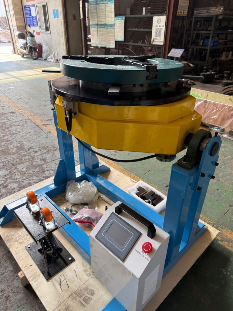
| Nozzles and small components | Head and tail positioners, three-axis positioners, turntables | Access and deposition rate in position |
A welding rotator earns its place when it can turn the shell at a controlled speed that matches the deposition rate. A rotator that surges leaves the arc in one place and produces uneven bead width, and roll width plus load rating decide whether the shell stays round under its own weight plus the welding head load.
A column and boom manipulator solves the other half of the problem, which is reach with rigidity. A boom that flexes under the welding head changes contact-tip-to-work distance along the seam, and that changes current density and penetration from one end of the weld to the other.
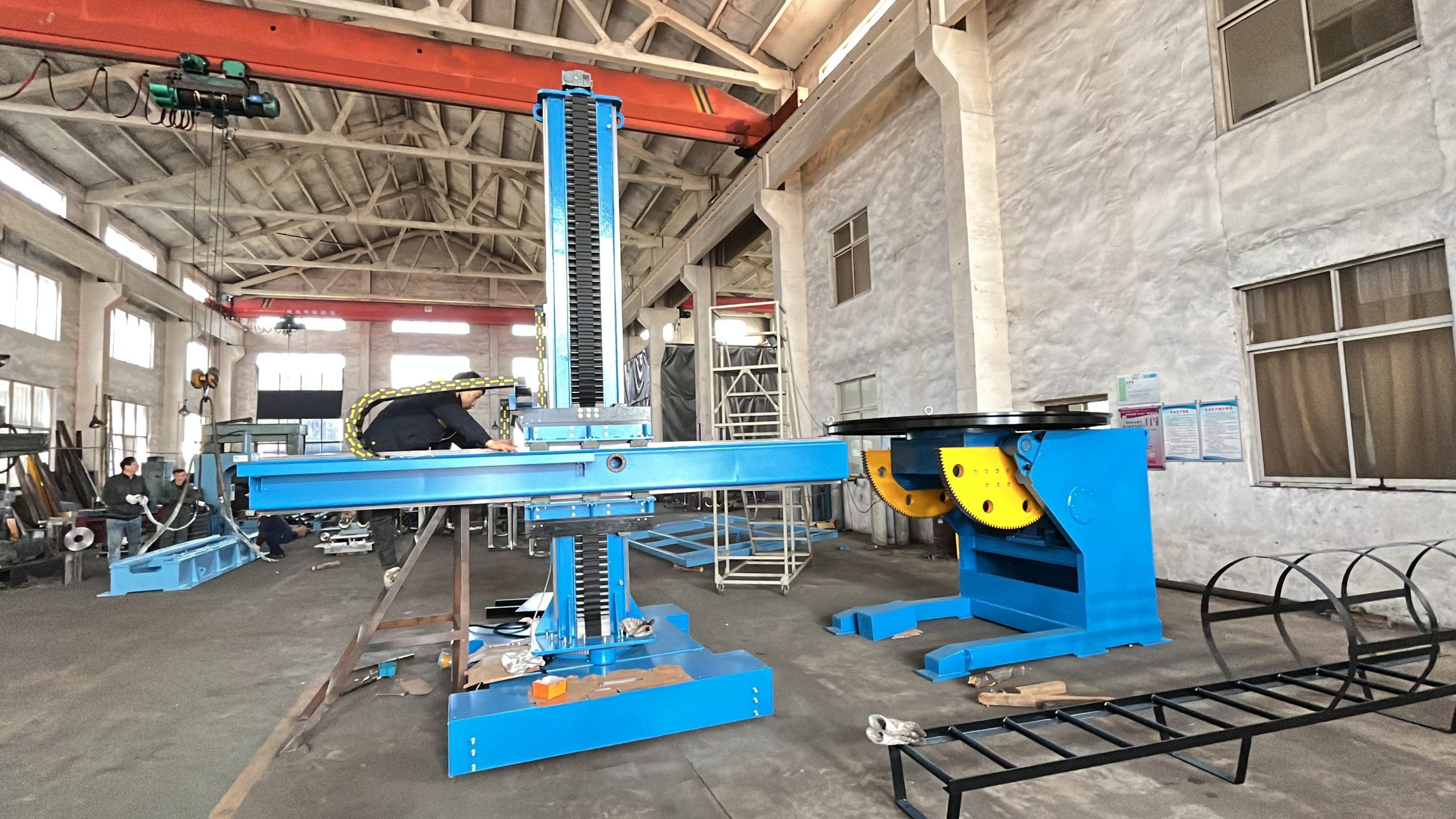
Long workpieces with a head or flange at both ends need the axis held while the part turns. A head and tail positioner does that with a chuck or faceplate at each end instead of a single cantilevered support.
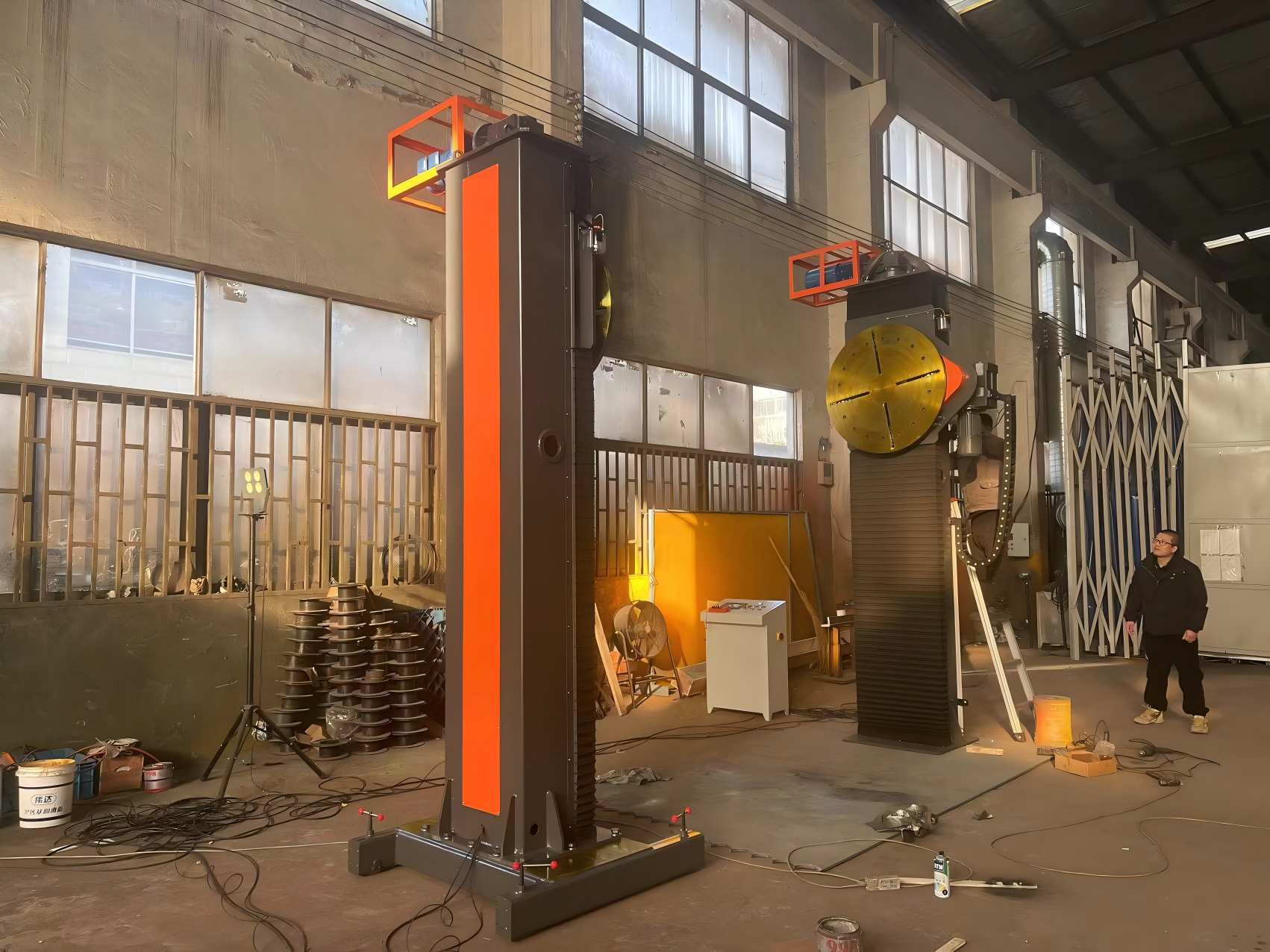
Suppliers who build rotators, positioners, manipulators and cutting machines for tank work normally quote capacity, roll width and reach as one package, because the three interact. WUXI ABK MACHINERY CO., LTD, for example, configures welding rotators, positioners, column and boom manipulators and CNC cutting machines as a matched set, which is the practical way to keep load ratings and reach consistent from cutting through to final seam.
Welding and inspection steps that prove the tank
How the weld sequence is set
Welding runs root, fill, then cap, and the process is chosen by position. Shell seams on a rotated tank stay in the flat or horizontal position, where submerged arc welding gives high deposition and deep penetration with one pass per side. Vertical joints on a field-erected shell are harder to automate: vertical-up flux-cored welding suits thick courses, and manual or semi-automatic work covers repairs and access-restricted joints. Each procedure is qualified to the standard named in the contract, typically ASME Section IX for the thickness range, process and position used [6].
Distortion control is a sequence problem more than a parameter problem. Balanced welding around the circumference, backstep on long seams and staggering of longitudinal seams between adjacent courses all reduce the pull on one side. Preheating is set by material grade and thickness, not by habit.
Rotating the shell so the seam stays in the flat or horizontal position is what makes submerged arc welding practical on a tank shell. <Column and Boom Manipulators for Large Vessel Precision Weldin> covers how column and boom manipulators position the head for large vessel welding.
When post-weld heat treatment is required
Above a nominal thickness of 32 mm (1.25 in.), carbon steel vessels under ASME Section VIII Division 1 require post-weld heat treatment [3]. That threshold is a design decision as much as a welding one. A shell designed just below it avoids a furnace or a field heat treatment, while a shell above it needs a procedure that controls distortion during heating, holding and cooling.
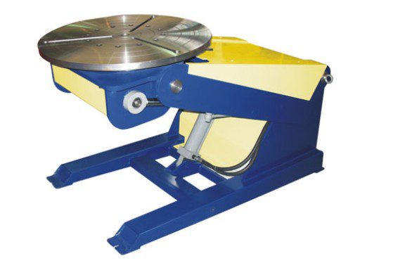
Nozzles and manways are small welds in awkward positions, and they are where operator fatigue shows first. A three-axis positioner tilts the part so the joint stays accessible and the torch angle stays stable through the pass.
What each inspection test proves
Inspection combines volumetric testing on butt seams, surface testing on corner welds, and a pressure test on the finished tank [1], [3]. The records matter as much as the tests, because each one supports a narrower conclusion than buyers usually assume.
| Record or result | What it actually covers | Legitimate use | Do not infer |
|---|---|---|---|
| Joint efficiency of 1.00 under ASME Section VIII Division 1 | That joint type, with full radiography over the specified extent [3] | Credit in the thickness calculation | That every weld on the vessel was fully radiographed |
| Hydrostatic test under API 650 | Tightness and structural behaviour at the test fill level [1] | Acceptance of the test and a settlement reference | Fitness for future service, corrosion allowance or a change of stored product |
| A procedure qualification on one plate grade and thickness range | That procedure, grade, thickness range and position [6] | Basis for production welding within the qualified range | Transfer to another grade or thickness without requalification |
| A rotator load rating stated by a supplier | Static capacity under the stated conditions | Screening equipment against shell weight | That the rating suits a shell with off-centre nozzles or an uneven centre of gravity |
Surface testing on the shell-to-bottom junction and vacuum box testing on bottom lap seams cover the joints that radiography cannot reach easily. Settlement readings taken at each fill stage give the baseline that later in-service inspection compares against [5].
What to fix in the RFQ before the first plate is cut
Most disputes in tank construction trace back to information that was missing at quotation stage, and the cost of adding it later is always higher than the cost of stating it once.
- Design basis: governing standard and edition, design metal temperature, stored product, corrosion allowance, design pressure or vacuum, wind and seismic criteria.
- Geometry: diameter, height, course thicknesses, roof type, nozzle schedule and the foundation interface.
- Welding and inspection: joint efficiency and radiography extent, post-weld heat treatment requirement, NDT methods and acceptance level, hydrostatic test requirement or agreed exemption.
- Equipment scope: shell weight and diameter range for rotators, reach and load for manipulators, positioner capacity for heads and nozzles, cutting table size for the largest plate.
- Documentation: welding procedure specifications and qualification records, material certificates with heat numbers, NDT reports, dimensional records and settlement readings.
The equipment line is the one buyers most often leave out. A rotator sized on shell weight alone can still be wrong when off-centre nozzles shift the centre of gravity, and a manipulator chosen on reach alone can be too flexible for the seam it has to weld.
Match the equipment package to your tank data
Send the governing standard and edition, design temperature and corrosion allowance, shell diameter and height, course thicknesses, roof type, joint efficiency and radiography extent, post-weld heat treatment requirement, the largest plate size, and the shell weight range you expect to rotate. Those fields set rotator capacity, roll width, manipulator reach and cutting table size together, and quoting them one at a time is how packages end up mismatched. Include site power supply and crane capacity if the welding will happen in the field.
Email [email protected] or call +86 13616174307 with the tank data and the weld positions you expect, and the equipment scope can be matched to your construction method rather than to a single machine rating.
FAQ
How long does steel tank construction take?
Schedule is set by weld length and inspection extent, not by tank diameter alone. A small shop-built tank with a few courses can be finished in weeks; a large field-erected tank with many courses, extensive radiography and a jacking sequence runs for months. The drivers are the number of courses, total seam length, NDT coverage, weather at the site and how much correction the fit-up allows. Ask for a schedule built from weld hours and inspection hours per course rather than a single completion date.
What is the difference between API 650 and ASME Section VIII?
API 650 covers field-erected atmospheric storage tanks. ASME Section VIII Division 1 covers pressure vessels, including tanks that operate above atmospheric pressure, and it adds rules such as joint efficiency credit and mandatory post-weld heat treatment above a thickness threshold [3]. The same physical tank can fall under either standard depending on design pressure and service, and the choice changes shell thickness, NDT extent and testing. Confirm the applicable scope with the purchaser and the local jurisdiction before quoting.
Is hydrostatic testing required for every tank?
Under API 650 the hydrostatic test is the normal acceptance test, and the standard sets limited conditions under which it can be waived with purchaser agreement and alternative examination [1]. A hydrostatic test proves tightness and shows how the foundation and shell behave under fill load. It does not prove fitness for future service and it does not replace radiography of the seams. Record settlement at each fill stage so the readings remain usable later under API 653 [5].
Why does the shell-to-bottom junction leak more often than shell seams?
Because it is a T-junction between a thin bottom plate and a thicker shell course, made under restraint, often late in the sequence, with limited access for testing. Shrinkage of the bottom pulls the shell inward while the corner weld is being deposited, so the joint sees movement during solidification. Cleaning, fit-up and sequence control matter more here than on a flat seam, and inspection usually combines penetrant or magnetic particle testing with a vacuum box check from the underside.
Can a large tank be fully shop fabricated?
Only up to the transport envelope. Beyond that, plates are cut and rolled in a shop and welded on site, and the practical question becomes where dimensional tolerance changes hands. If the shop rolls the courses and the site fits them, agree the measurement method and the acceptance limits at handover, including how ovality will be measured and what happens to courses that arrive outside the agreed band.
References
[1] API Std 650, “Welded Tanks for Oil Storage,” 13th ed., American Petroleum Institute, 2020.
[2] API Std 620, “Design and Construction of Large, Welded, Low-Pressure Storage Tanks,” 12th ed., American Petroleum Institute, 2013.
[3] ASME BPVC Section VIII, Division 1, “Rules for Construction of Pressure Vessels,” ASME, 2023.
[4] EN 14015:2004, “Specification for the design and manufacture of site built, vertical, cylindrical, flat-bottomed, above ground, welded, steel tanks for the storage of liquids at ambient temperature and above,” CEN, 2004.
[5] API Std 653, “Tank Inspection, Repair, Alteration, and Reconstruction,” 5th ed., American Petroleum Institute, 2018.
[6] ASME BPVC Section IX, “Welding, Brazing, and Fusing Qualifications,” ASME, 2023.
If you’re interested, check out these related articles:
Precision Positioning for Pipe and Shaft Welding Workpieces
CNC Water Jet Cutting: Precision, No Heat, Any Material
CNC Flame Cutting: Precision Cutting for Heavy Plate Fabrication
Achieve Production Success With One-Stop Welding Automation
Fit-Up Rotator for Accurate Vessel Alignment & Stable Welding