Pressure Vessel Welder: How It Works and Key Configurations
Table of Contents
- What Is a Pressure Vessel Welder
- How Does a Pressure Vessel Welding System Work
- Key Components of a Pressure Vessel Welder
- Column and Boom Manipulator
- Welding Rotators and Turning Rolls
- Welding Power Source and Control System
- Flux Recovery and Delivery
- How to Choose the Right Pressure Vessel Welder for Your Shop
- Vessel Diameter and Weight Range
- Automation Level and Integration
- After‑Sales Support and Documentation
- Matching Your Vessel Production Equipment to Long‑Term Demand
- Common Questions About Pressure Vessel Welding Systems
- Can a pressure vessel welder handle both longitudinal and circumferential seams?
- Is submerged arc welding (SAW) the only process used on pressure vessel welders?
- What safety features should a properly designed system include?
- How important is flux recovery in daily operation?
Pressure vessel welders are automated systems that weld the longitudinal and circumferential seams of large cylindrical tanks and pressure vessels. They combine a welding manipulator, turning rolls, and a welding power source to move the arc precisely along the joint while the workpiece rotates under controlled speed. For fabrication shops that produce boilers, storage tanks, chemical reactors, or wind tower sections, understanding how these integrated machines function is the first step toward reducing manual labor, improving bead consistency, and meeting code requirements. This article explains the operating principle, the core components, and the practical configuration factors you need to evaluate when selecting a pressure vessel welding system for your production line.
What Is a Pressure Vessel Welder
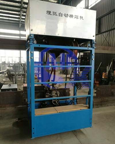
A pressure vessel welder is not a person. It is a stationary or traveling automated welding station built specifically for joining the heavy wall plates that form pressure‑containing vessels. The system typically uses submerged arc welding (SAW) or gas metal arc welding (GMAW) and is engineered to handle shell diameters from under one meter to over six meters, with wall thicknesses reaching 50 mm or more. The welding head rides on a column and boom manipulator that provides vertical and horizontal travel, while motorized turning rolls rotate the vessel at a fixed speed matched to the welding parameters.
These welding stations are common in facilities that fabricate ASME Section VIII pressure vessels, API 650 storage tanks, heat exchangers, and wind turbine towers. Their primary value is repeatability: a properly set up pressure vessel welder delivers the same penetration profile and deposition rate on a 12‑meter seam that it does on the first 100 millimeters, eliminating the variability that even skilled manual welders cannot avoid over long continuous welds.
How Does a Pressure Vessel Welding System Work
The operating principle is straightforward but depends on precise coordination between rotation and travel. The vessel shell is placed on a set of powered and idler turning rolls, aligned so the weld joint – longitudinal or girth – passes directly under the welding head. For a longitudinal seam, the manipulator arm extends over the top of the stationary vessel, and the SAW head travels along the seam while the flux delivery system blankets the arc. For a girth seam, the turning rolls rotate the vessel while the welding head stays fixed at the 12‑o’clock position, welding a continuous circumferential joint.
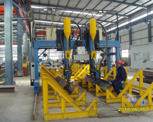
In high‑volume production lines, two SAW heads can operate simultaneously on opposite sides of the same joint, running in tandem to double the deposition rate. The rotation speed is set based on wire feed speed, voltage, and the desired bead width, and the entire sequence – start, arc ignition, travel, crater fill, stop – is controlled by a PLC to ensure every weld pass follows the same parameters. Fit‑up rotators are often used earlier in the process to align shell courses and tack the joint before the vessel moves to the automatic welding station, because poor fit‑up is the fastest way to create lack‑of‑fusion defects in an otherwise well‑designed automated weld.
Key Components of a Pressure Vessel Welder
The function of the machine is distributed across several coordinated components. Understanding each one helps when comparing supplier proposals.
Column and Boom Manipulator
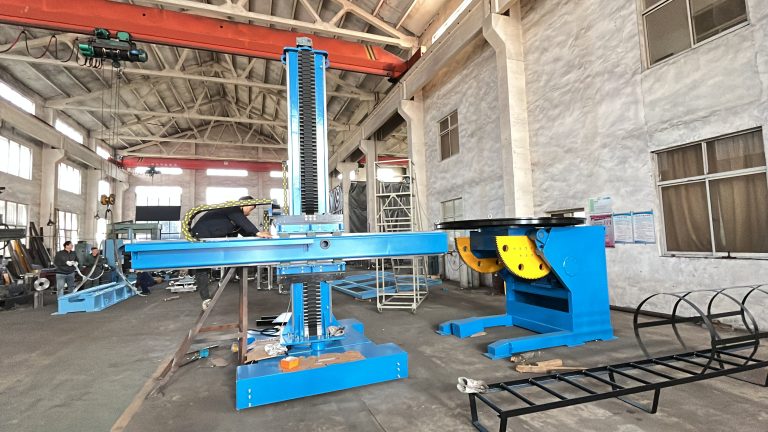
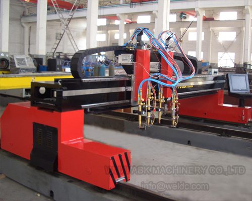
The manipulator carries the welding head and provides vertical and horizontal positioning. Boom length determines the maximum vessel diameter the station can reach, while column height sets the vertical range. Rigidity matters: any deflection in the boom during long seams introduces arc length variation and changes penetration. For internal longitudinal welds on vessels over 3 meters in diameter, an extended boom with a rotating welding head may be necessary to reach the bottom of a deep shell.
Welding Rotators and Turning Rolls
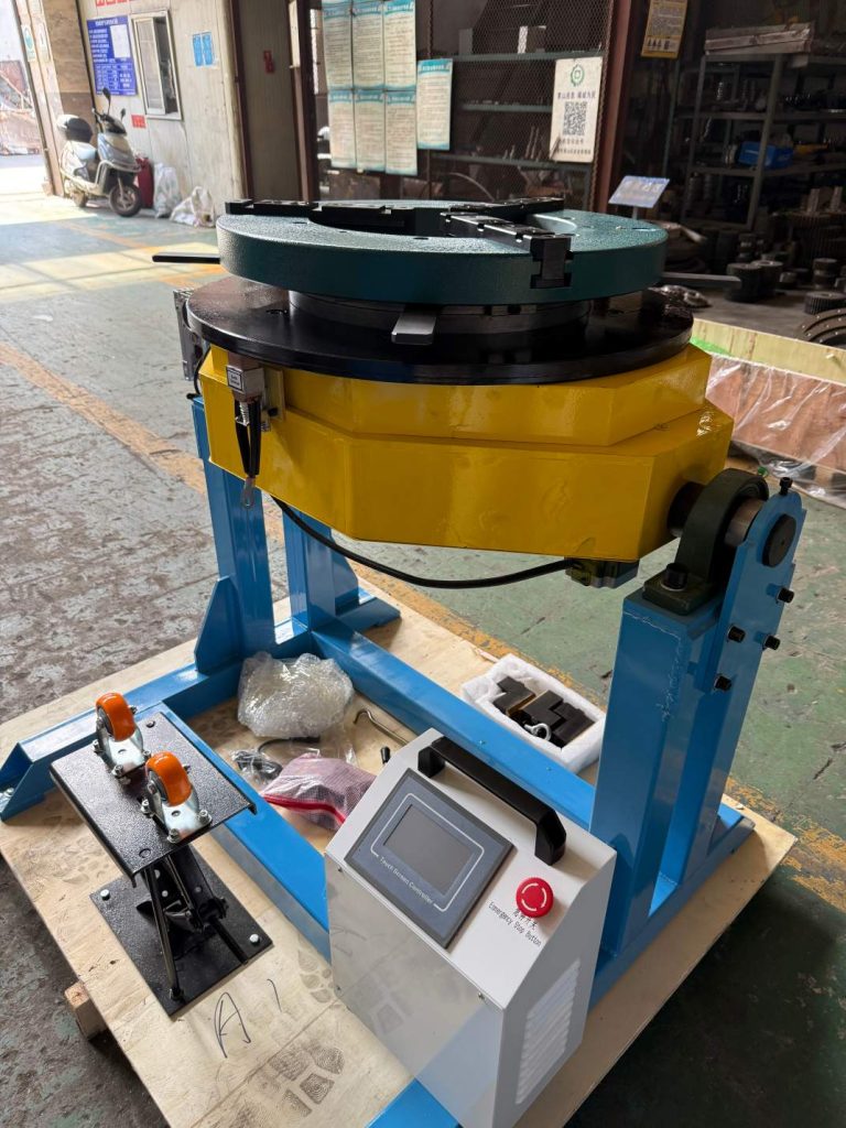
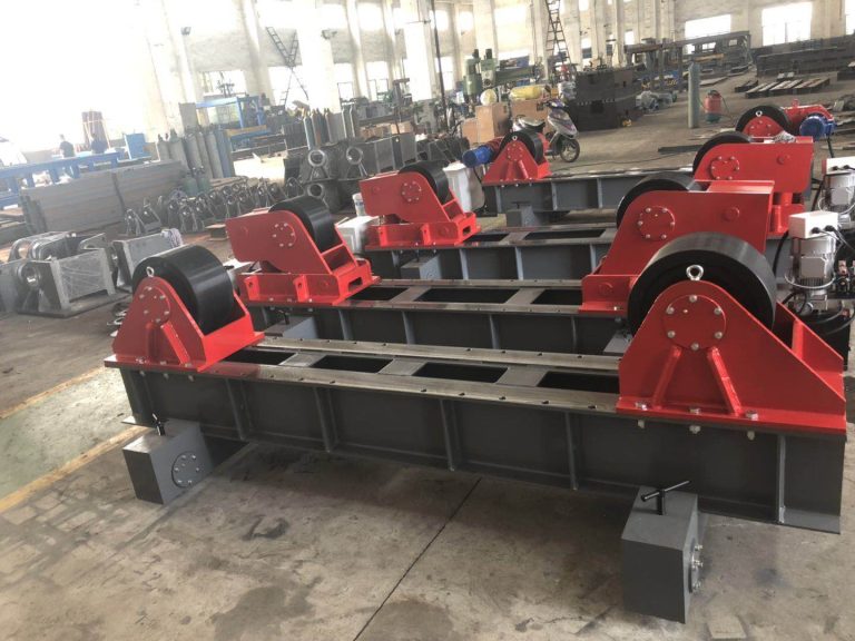
The turning rolls support and rotate the vessel at a controlled speed. The roll material – steel, polyurethane, or rubber‑lined – is chosen based on the workpiece surface finish and weight. Self‑aligning rotators accommodate a range of diameters without manual adjustment, which saves changeover time in shops that produce multiple vessel sizes. Load capacity must include not just the vessel weight but the additional down‑force from the welding head and flux bed.
Welding Power Source and Control System
The power source, typically a 1000‑amp or higher SAW unit, is integrated with the PLC that controls travel speed, rotation start/stop, and arc parameters. The control panel allows the operator to set wire feed speed, voltage, travel speed, and rotation speed, and to store welding procedure specifications (WPS) for different material grades and thicknesses. A reliable control system is what turns a collection of mechanical components into a repeatable production tool.
Flux Recovery and Delivery
In submerged arc welding, a layer of granular flux covers the arc. A flux delivery hopper feeds the joint ahead of the arc, and a vacuum recovery unit collects unfused flux after the weld for reuse. Maintaining consistent flux depth is critical for preventing porosity and slag entrapment, so the delivery system must be synchronized with travel speed.
How to Choose the Right Pressure Vessel Welder for Your Shop
Selecting the right equipment begins with an honest assessment of your current and planned production range, not just the largest vessel you have on the floor today.
Vessel Diameter and Weight Range
The turning rolls and manipulator must be sized for the smallest and largest shell diameters you expect to weld. If your production mix includes thin‑wall stainless steel tanks as well as heavy carbon steel boilers, you need rotators that can handle both weight extremes without causing surface damage on the lighter vessels. As a rule, calculate the weight of the heaviest vessel with all internals and a full flux load, then add a 20‑30% margin.
Automation Level and Integration
A basic pressure vessel welder moves the head manually to position and then runs the weld seam automatically. More advanced systems include seam tracking, which adjusts the welding head in real time to follow the joint even if the shell is slightly out‑of‑round. In my experience, shops that invest in seam tracking see a measurable reduction in weld repair rates on long girth seams where small misalignments are common. If you plan to integrate the welding station into a larger production line with upstream plate beveling and downstream heat treatment, the control interface must communicate with your overall production planning system.
After‑Sales Support and Documentation
Because a pressure vessel welder is a custom‑engineered system, not an off‑the‑shelf product, the quality of the supplier’s documentation matters as much as the machine itself. Ask for a detailed operation manual, maintenance schedule, and spare parts list before signing a contract. Verify that the supplier can support voltage and frequency requirements at your specific location, and confirm whether commissioning and operator training are included.
Matching Your Vessel Production Equipment to Long‑Term Demand
Every fabrication shop eventually faces the same tension: the vessel sizes you produce today may not be the ones your customers request two years from now. A pressure vessel welding system sized only for current work can become a bottleneck that forces you to turn away larger, more profitable contracts. The most practical approach is to specify a manipulator and rotator set that covers a diameter range broad enough to absorb future growth without significantly overinvesting today.
We work with pressure vessel fabricators across more than 40 countries to configure welding automation systems that fit their current production floor and their long‑term capacity goals. If you are planning a new pressure vessel welding line or upgrading an existing setup, send your vessel diameter range, wall thickness, and production volume to [email protected] or call +86 13616174307, and we will provide a configuration proposal with the supporting technical documentation you need to make an informed decision.
Common Questions About Pressure Vessel Welding Systems
Can a pressure vessel welder handle both longitudinal and circumferential seams?
Yes, nearly all industrial pressure vessel welding stations are designed for both. A longitudinal seam is welded by traversing the welding head along the length of the stationary vessel on the turning rolls. A girth seam is welded by fixing the welding head at the correct position and rotating the vessel. The control program simply switches the axis that provides the travel motion – boom travel for longitudinal, roll rotation for girth – without any mechanical changeover.
Is submerged arc welding (SAW) the only process used on pressure vessel welders?
SAW dominates because of its high deposition rate and deep penetration on thick plates, making it the most productive choice for heavy‑wall vessel seams. However, many shops also use gas metal arc welding (GMAW) heads on the same manipulator for root passes or for thinner sections where SAW’s heat input would be excessive. Dual‑wire SAW and tandem SAW are common variations for increasing productivity on very long seams.
What safety features should a properly designed system include?
Load‑holding safety locks on the column and boom prevent unintentional lowering in case of power loss. An emergency stop circuit that kills all motion – boom travel, roll rotation, and wire feed – must be wired to multiple access points along the station. The turning rolls should have anti‑drift control to prevent axial movement of the vessel during rotation, which could allow the shell to walk off the rolls.
How important is flux recovery in daily operation?
It affects both cost and weld quality. A vacuum recovery unit that continuously collects, screens, and recirculates unfused flux reduces consumable waste by 30‑40% compared to manual flux cleaning. More importantly, it prevents slag inclusions caused by reusing contaminated flux. For a shop running multiple shifts, automated recovery pays for itself within months. Share your throughput expectations, and we can confirm which flux system capacity matches your daily consumption.
If you’re interested, check out these related articles:
Heavy-Duty Welding Rotators with 200 Ton Load Capacity
Achieve Production Success With One-Stop Welding Automation