Pressure Vessel Fabrication: Design, Types, and Welding Tips
Table of Contents
- Design Inputs That Decide Pressure Vessel Fabrication Success
- Pressure Vessel Types and Fabrication Demands
- Welding Equipment and Seam Access for Vessel Shells
- Qualification, Inspection, and Documentation Requirements
- Pre-Order Checks for Pressure Vessel Welding Equipment
- Common Questions About Pressure Vessel Fabrication
- Does ASME Section VIII cover all pressure vessels?
- How accurate does shell roundness need to be before girth welding?
- When should a vessel shop choose a welding manipulator instead of manual welding?
- What information do we need to send before ordering vessel welding equipment?
Pressure vessel fabrication fails less often in the design calculation stage and more often at the seam, the fit-up point, or the rotation step. As a welding automation engineer, I evaluate vessel drawings by looking for buildability: shell ovality limits, seam access, nozzle spacing, and whether the shop can rotate the assembly safely during welding. This article covers the design inputs that should be settled before procurement, the vessel types that drive different equipment choices, and practical welding and inspection requirements. The goal is to connect code-compliant design with shop-floor welding decisions so that the finished vessel is both sound and efficiently produced.
Design Inputs That Decide Pressure Vessel Fabrication Success
A vessel drawing may meet the allowable stress rules and still be difficult to build if the fabricator cannot reach the seam or control the joint gap. Three design inputs matter most for shop-floor execution: shell diameter and length, joint configuration, and fabrication tolerance. Thin-wall shells are more prone to ovality during handling; thick-wall shells bring preheat and post-weld heat treatment requirements. Each of these inputs changes the welding automation approach before a single weld is made.
Code selection should be fixed at the design stage. ASME Section VIII Division 1, EN 13445, and PED all set different joint efficiency, material, and inspection rules. A buyer who leaves the governing code open until quotation may receive two equipment lists that cannot be compared. For shops building vessels for European clients, CE marking and ISO 3834 welding quality management often become part of the package. Fabrication tolerances such as shell roundness and weld bevel angle should appear on the drawing or in a fabrication specification, not be left to the shop.
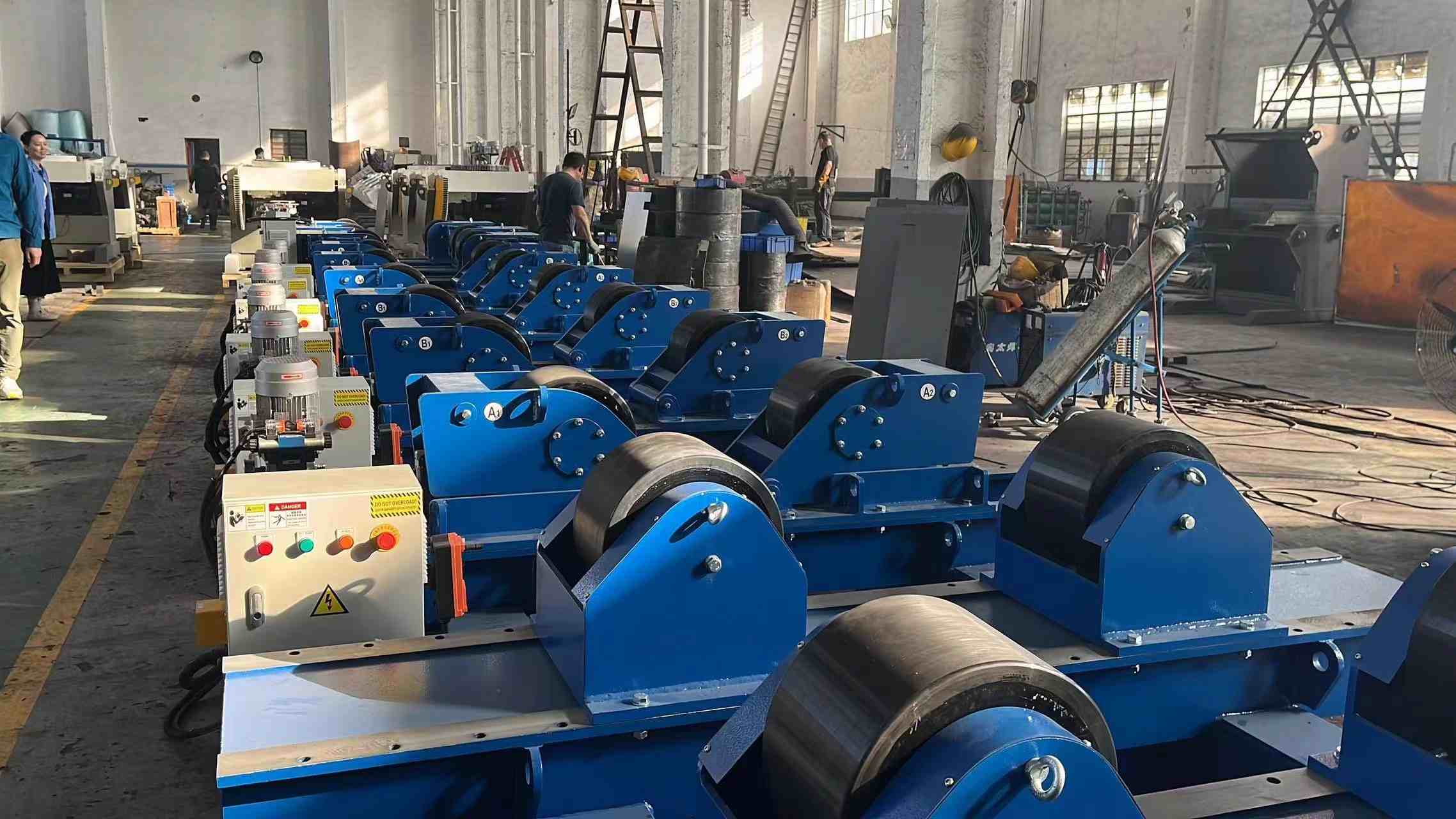
I have watched shell fit-up problems turn a one-day longitudinal seam into three days of grinding and rework. The mechanism is usually simple: a rolled course that is slightly oval or a bevel angle that varies along the seam creates an uneven root gap, so the automated arc burns through in one section and lacks penetration in the next. When the root pass needs repair, every following pass is delayed. I ask shops to check roundness and bevel consistency before the first automated weld, because rework at the root stage is far more costly than adjusting the plate before fit-up.
Pressure Vessel Types and Fabrication Demands
Pressure vessel procurement usually begins with a service condition, not a shape. Storage bullets, heat exchanger shells, reactors, and process columns all share cylindrical geometry, but their welding sequences differ because of wall thickness, nozzle density, and internal components. The first equipment decision follows from the vessel type and the seam length rather than from the material alone.
| Vessel type | Typical construction | Welding equipment requirement |
|---|---|---|
| Storage bullet | Cylindrical shell with formed heads | Fit-up rotators to control joint gap during tacking |
| Heat exchanger shell | Long cylinder with tube sheets and nozzles | Welding manipulator for longitudinal seams; rotator for girth seams |
| Reactor vessel | Thick-wall shell with internals and cladding | Heavy-duty rotators and overlay-capable manipulators |
| Process column | Multi-course shell with tray supports | Column and boom system with turning rolls |
| LPG vessel | Cylindrical or spherical plate construction | Fit-up jigs and multi-axis positioners for curved sections |
Thin-wall storage vessels often tolerate simpler rotation, but long heat exchanger shells create a different problem: the length makes the shell deflect between supports. A fixed-height rotator set without checking roller center distance can load the shell unevenly and produce weld bead wander on the girth seam. For thicker reactor and column sections, preheat and interpass temperature control matter more than rotation speed. The equipment plan should therefore follow the vessel’s stiffness and thermal mass, not a generic tonnage rating.
Welding Equipment and Seam Access for Vessel Shells
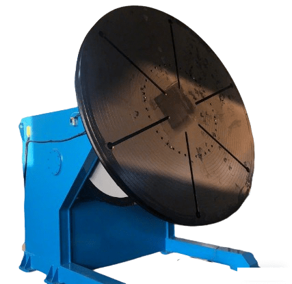
Longitudinal seams and girth seams place different demands on automation. A longitudinal seam is easier to reach with a column and boom manipulator, but the weld length requires consistent travel speed and torch angle. A girth seam is shorter in linear distance but depends on rotation speed stability; if the rotator stutters or the shell rolls off center, the weld bead becomes irregular and the arc time increases.
For smaller diameters, seam access changes the welding process choice. When a welder cannot physically enter the shell, the root pass is often placed from the outside with GTAW or a controlled short-circuit process, and the remaining passes may use submerged arc welding from the outside. On large-diameter vessels, internal access permits double-sided welding, but the shop now needs a rotator that can turn the shell at the exact speed for each process. The same machine that works for SAW may be too fast or too slow for TIG root welding unless the drive has a wide speed range.
Nozzle and manway placement is where design and welding access most often conflict. A nozzle that sits close to a longitudinal seam or a manway reinforcement that covers a girth seam turns a simple automated pass into a series of manual restarts. I have seen nozzle spacing specified without accounting for the manipulator head width; the drawing looked code-compliant, but the shop had to stop the boom travel and complete the seam by hand. The result was a visible repair point and a longer inspection record. Design reviews should put nozzle weld clearances into the same checklist as the mechanical calculations.
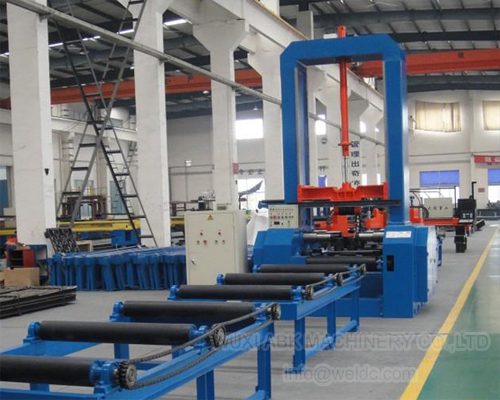
If your vessel program involves diameters below 400 mm, wall thickness above 30 mm, or nozzle clusters near seams, confirm seam access and rotator speed range before finalizing the equipment list. Send vessel diameter, shell length, and empty weight to [email protected] and we can check which rotation and manipulator configuration fits your weld map.
Qualification, Inspection, and Documentation Requirements
Vessel welding does not end with a visually acceptable seam. Most pressure vessel standards require a qualified weld procedure, a documented welder qualification, and non-destructive examination before hydrostatic testing. The specific NDE method depends on the joint location and material: full penetration butts often receive ultrasonic testing, while surface standards may call for magnetic particle or liquid penetrant testing. A shop that cannot show traceable procedure qualification records from a previous vessel project will struggle during the audit, regardless of how clean the weld appears.
Post-weld heat treatment and hydrostatic testing are the two events where hidden fabrication errors become schedule delays. If the welding procedure did not control heat input on a thick shell, the PWHT cycle may reveal delayed cracking risk or unacceptable distortion. If the shell was not centered on the rotator during fit-up, the nozzle positions may shift enough to fail a dimensional check after pressure testing. These are the moments when a low-cost equipment choice shows its real cost.
Documentation should include material certificates, weld maps, procedure qualification records, NDE reports, and the hydrostatic test report. For buyers sourcing from China, factory inspection before shipment can verify that the records match the physical vessel. Wuxi ABOKE Machinery holds ISO and CE certifications and applies European-oriented quality control to its welding and cutting equipment, which gives vessel fabricators a documentation trail when they are building for audited supply chains.
Pre-Order Checks for Pressure Vessel Welding Equipment
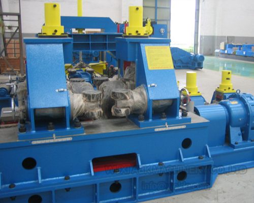
Many pressure vessel fabricators discover automation gaps after the plates are cut and the shell is ready for fit-up. The equipment list may include a rotator, but not the adjustable roller centers or the speed range to handle both GTAW and SAW. Or the manipulator boom is long enough for the vessel diameter but not for the nozzle weld offsets. These gaps show up as schedule pressure at the worst point in the project.
Before ordering, confirm the diameter range, maximum shell weight, seam length, and the process you plan to run for root, fill, and cap passes. Send these four values to [email protected] or call +86 13616174307, and we will check whether the rotator, manipulator, and fit-up configuration match the vessel’s weld map. The response is a specific equipment list and gap review, not a product brochure.
Common Questions About Pressure Vessel Fabrication
Does ASME Section VIII cover all pressure vessels?
No. ASME Section VIII is common, but other codes apply depending on location and service. EN 13445 and the Pressure Equipment Directive apply in many European supply chains, and certain storage, process, or transport vessels fall under other codes. The governing code changes weld joint design, NDE requirements, and documentation. Buyers should state the code in the inquiry, because a vessel designed for one set of rules cannot always be reclassified later without recalculating the shell and revising procedure qualifications.
How accurate does shell roundness need to be before girth welding?
The practical limit depends on shell diameter and wall thickness, but the joint gap variation must stay within the welding procedure’s tolerance. For thin-wall large-diameter shells, ovality beyond a few millimeters makes the root gap open or close around the circumference. That condition forces the welder to adjust parameters mid-seam, which increases the chance of lack of fusion or burn-through. Shops that use fit-up rotators can check the gap while rotating the shell before tacking the next course. This is faster than cutting and re-rolling after the seam is underway.
When should a vessel shop choose a welding manipulator instead of manual welding?
The better question is whether the seam length and pass count justify the setup time. Manual welding is still practical for short, interrupted seams around nozzles and attachments. For longitudinal seams over several meters, a column and boom manipulator keeps torch angle and travel speed constant across the full pass. That consistency matters more on thick shells where multiple submerged arc passes must overlap evenly. A manipulator also removes the operator from a confined position. If the vessel has long straight seams or repeated circumferential welds, automation usually pays back through fewer repair points and shorter arc time.
What information do we need to send before ordering vessel welding equipment?
When a fabricator sends only the vessel diameter and tonnage, we usually have to ask for three more values. Shell length determines roller center distance. Wall thickness and joint design determine whether preheat control and a slower rotational speed matter. The weld process, whether GTAW, SAW, or FCAW, sets the speed range and torch access requirements. Without these inputs, the quotation may fit the load but not the operation. Send a vessel diameter range, maximum shell length, wall thickness, and empty weight to [email protected], and we will confirm which rotator and manipulator configuration matches your weld map.
If you’re interested, check out these related articles:
L-Type Welding Positioners: Applications and Load Capacity Guide
Adjustable Welding Rotator for Different Diameter Vessel Welding
Offshore Wind Tower Fabrication: Key Equipment and Main Challenges
Welding Manipulators for Storage Tanks: Girth and Seam Automation
Automatic Welding Centers Improve Production Efficiency & Weld Quality